Owner's Manual SNOW BLOWER HS50 ©1983 Honda Motor Co., Ltd.
Thank you for purchasing a Honda snowblower. This manual covers operation and maintenance of the HS.50 snowblower. All information in this publication is based on the latest product information available at the time of approval for printing. Honda Motor Co., Ltd. reserves the right to make changes at any time without notice and without incurring any obligation. No part of this publication may be reproduced without written permission. This manual should be considered with the snowblower when sold.
/ CONTENTS 1. SAFETY ....................................... 2. COMPONENT IDENTIFICATION AND FUNCTION ..... ............................... Engineswitchknob Fuel valve knob ................................... ..................................... Chokeknob Starter grip ...................................... Throttle lever .................................... Shift lever ....................................... Auger clutch lever and drive clutch lever ............... Chute crank .........................
1. SAPETY To ensure safe operation * Read this owner’s manual thoroughly and understand the operating procedure before using the snowblower. Never permit anyone to operate the snowblower without proper instructions. * Do not allow children to operate the snowblower. Keep children and pets away from the area of operation. * Be properly dressed in winter clothing. Wear slip-proof winter boots. * Before operating the snowblower, inspect the area you are going to clear of snow.
* Adjust the snow chute to avoid hitting bystanders, windows, etc. with thrown snow. Stay clear of the discharge opening. * While operating the snowblower, always hold the handle firmly and walk. Don’t run. * If people or pets suddenly appear in front of the snowblower, while it is in operation, immediately release the auger and drive clutch levers., * When you hit an obstacle while operating the snowblower, stop the engine immediately and check the machinery for damage.
* Exhaust gas contains poisonous carbon monoxide. Never run the snowblower in an enclosed area. Be sure to provide adequate ventilation. * Gasoline is extremely flammable and explosive under certain conditions. Refuel in a well ventilated area with the engine stopped. * When transporting the snowblower, turn the Fuel valve OFF and keep the snowblower level to prevent fuel spillage.
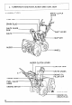
2.
Q TRACK TYPE > SHIFT LEVER DRIVE CLUTCH SPARK PLUG CHUTE GRIP GUIDE AUGER CLUTCH I CHUTE LEVER CRANK STARTER GRIP INE OIL mER CAP CHOKE KNO ENGINE SWITCH HEIGHT ADJUST MENT PEDAL -SKID PLATE ENGINE OIL DRAIN PLUG
ENGINE SWITCH KNOB Use the engine switch to START and STOP the engine. ENGINE \ I-lriif SWITCH KNOB FUEL VALVE KNOB This knob opens and closes the fuel line leading from the fuel tank to the carburetor. Make sure that the knob is positioned exactly on either the ON or OFF position. LLL’ i ~/JE~VALVE KNo8’l I I I NOTE: Before transporting snowblower be sure to turn the knob to OFF to prevent possible fuel leaks.
CHOKEKNOB Use the choke knob when the engine is cold or difficult to start. OPEN CiiOKE I ’ KNOti” STARTERGRIP Pull this grip to start the engine.
THROTTLE LEVER (ENGINE SPEED) Use the throttle position. lever to select the engine speed. In normal operation, ROTTLE SHIFT LEVER Use the shift lever to select drive speed or direction.
AUGER CLUTCH LEVER AND DRIVE CLUTCH LEVER Use these controls to engage the snow blowing mechanism and/or the drive mechanism. DRIVE AUGER CLUTCH LEVER Squeeze to engage the snow blowing mechanism. CLUTCH ueese to engage the ve mechanism. NOTE: When both levers are squeezed, the drive clutch lever locks the auger clutch lever down. Releasing the drive clutch lever then unlocks and releases the auger clutch lever. Both levers squeezed.
CHUTECRANK Use the chute crank to turn the snow discharge chute right or left. To throw snow to the left CHUTE CRANK CHUTEGUIDE The chute guide controls the snow discharge angle.
SKID PLATE Adjust the skid plates for the auger housing ground clearance best suited to your snow removal conditions. AUGER HOUSING SNOW REMOVAL CONDITIONS For general use For use on uneven surfaces For use on flat surfaces GUARD RECOMMENDED AUGER HOUSING GROUND CLEARANCE 6- lo-30 0- 8 mm (0.24-0.31 in) mm (0.39-1.18 in) 5 mm (O-0.20 in) NOTE: Track model only - The position of the height adjustment pedal (p. 14) also affects auger housing ground clearance.
HEIGHT ADJUSTMENT PEDAL (Track model only) Use the pedal for adjusting the height and angle of the machine in relation tracks. 1. Hold the handles and step on the pedal. 2. Raise or lower the machine to the desired position and release the pedal. LOW MIDDLE : : Normal use HIGH : Deep snow or for transporting the HS50 HEIGHT PEDAL Hard snow or fine finish ADJUSTMENT LOW MIDDLE .
3. PRE-OPERATION CHECK FUEL LEVEL Inspection: Unscrew the fuel cap. Check the fuel level. Refueling: Use any regular grade automotive gasoline (unleaded gasoline is preferred) with a pump octane rating of 86 or’higher. Never use an oil/gasoline mixture. Prevent dirt, dust or water from entering the fuel tank. CAUTION: Gasoline substitutes are not recommended: they may be harmfull to the fuel system components. FUEL TANK CAPACITY: 3.5 Q (0.92 US gal, 0.77 Imp. gal.
ENGINE OIL LEVEL Inspection: With the snowblower on a level surface, remove the oil filler cap and check the oil level. If the level is low, fill to the top of the oil filler neck with the recommended oil. Oil filler neck OIL CAPACITY: RECOMMENDED -20 1 '-30 0 -20 20 -10 40 o W’F 1 1ooc 0.7, P (0.74 US qt, 0.62 Imp. qt) I OIL: Use high detergent, premium quality motor oil certified to meet or exceed U.S.
4. STARTING THE ENGINE 1. Turn the engine switch to the ON position. Engine switch 2. Turn the fuel valve to the ON position.
3. In cold weather and when the engine is cold, turn the choke knob to the CLOSE position. CHOKE’KNOB 4. Pull the starter grip lightly until you feel resistance, then pull briskly. ARTER GRIP NOTE: Don’t allow the rope to snap back; return it gently by hand. Otherwise, the starting mechanism might be damaged. While the engine is in operation, don’t pull the starter grip or damage may result.
c 5. Let the engine warm up for several minutes. If the choke has been turned to the CLOSE position, return it gradually to the OPEN position as the engine warms up.
5. ) SNOWBLOWER OPERATION 1. Raise the throttle lever (p. 10) to the high position for normal operation. 2. Move the shift lever (p. 10) to select the desired drive speed. DRIVE SPEED WITH LEVER IN THE HIGH POSITION 1 ~~~~ Wheel type _ r 1 ’ 1 0.32 m/s (1.05 ft/s) 2 0.50 m/s (1.64 ft/s) 3 0.74 m/s (2.43 ft/s) I ! 1 R 1 0.49 m/s (1.6 1 ft/s) 1 I Track tvne - . 11 0.21 m/s (0.69 ft/s) 0.33 m/s (1.08 ft/s) 0.48 m/s (1.57 ftls), . 1 0.33 m/s (1.
NOTE: To move the machine without engaging the snow blowing mechanism, squeeze the drive clutch lever only. Do this when moving the machine to or from the area to be cleared. l To engage the snowblowing mechanism without using the drive mechanism, squeeze the auger clutch lever only. Do this if you wish to maneuver the machine manually while clearing snow. l Squeeze both levers to propel the machine and clear snow simultaneously.
6. STOPPING THE ENGINE 1. Turn the engine switch to the OFF position. ENGINE 2. Turn the fuel valve to the OFF position. FUEL.
l------- 7. MAINTENANCE --- The purpose of inspection and maintenance is to keep the snowblower operating condition. Inspect or service as scheduled in the table on the next page. ~j ”I in the best Shut off the engine before performing inspection and maintenance, and remove the spark plug wire from the plug so the engine cannot be started. If the engine must be run, make sure the area is well ventilated. The exhaust contains poisonous carbon monoxide gas.
MAINTENANCESCHEDULE ’ Auger clutch cable Drive clutch cable Adjust Track Adjust Auger and blower *c3 Adjust Check *@I 0 0 0 Apply oil V-Belt Check *o Friction disc rubber Check w Friction disc shaft Apply oil Nuts, bolts, fasteners Check Fuel tube Replace *0 0 Everv 3 year * These items should be serviced by an authorized Honda dealer, unless the owner has the proper tools and is mechanically proficient. See the Honda Shop Manual for service information.
TOOL KIT ul ( 0 Spark plug wrench 1 Wrench handle 14x10 mm wrench 14x12 mm wrench Tool bag 25
ENGINE OIL CHANGE Drain the oil while the engine is still warm to assure rapid and complete draining. 1. Remove the drain plug and filler cap, and drain the oil. Retighten the plug securely. 2. Fill the crankcase with the recommended oil (see page 18) and check the level. OIL CAPACITY: 0.7 i? (0.74 US qt, 0.
SPARK PLUG SERVICE Recommended spark plug: BR-4HS (NGK) W 14FR-U (ND) To ensure proper engine operation, the spark plug must be properly gapped and free of deposits. 1. Remove the spark plug cap. 2. Use the wrench supplied in the tool kit to remove the spark plug. 3. Visually inspect the spark plug. Discard it if the insulator is cracked or chipped. 4. Measure the plug gap with a feeler gauge. The gap should be 0.6-0.7 mm (0.024-0.028 in). Correct as necessary by bending the side electrode. 5.
TRACK - ADJUSTMENT (Track model only) ADJUSTMENT INTERVAL: Every year, before operation. CHECKING PROCEDURE: Tilt the snow thrower right or left and keep the track free. Check that the track isn’t deflect naturally and adjust it if necessary. 8 mm BOLT CRAWLER ADJUSTMENT 1. Loosen the 8 mm bolt on the rear track wheel on each side of the snow thrower. 2. Loosen left and right tension bolt lock nuts, and adjust the tension bolts to obtain the correct track deflection. 3.
I I 8. STORAGE / i- i Before storing the snowblower for an extended period: 1. Be sure the storage area is free of excessive humidity 2. Drain the fuel - and dust. m Gasoline is extremely flammable and explosive under certain conditions. Do not smoke or allow flames or sparks in the area. FUEL ‘VALVE a. Drain the fuel. CARBURETOR DRAIN SCREW b. Loosen the carburetor drain screw, and drain the gasoline into a suitable container. Retighten the drain screw after all gasoline has been drained.
Remove the spark plug and pour three tablespoonsful of clean motor oil into the cylinder. Pull the starter rope slowly two or three times to distribute the oil. Reinstall the spark plug. Pull the starter grip until resistance is felt. This closes the valves and breaker points, and protects them from dust and corrosion.
Apply oil to the following parts for lubrication CHUTE ADJUSTING BOLT and rust prevention.
-l FRICTION DISK SHAFT 1. With the fuel tank drained, turn the chute forward and stand the snow thrower on end as shown. BOTTOM 2. Remove the bottom 3. Oil the friction disk shaft. Never oil the friction disk and dl disk. 4. Install the bottom COVER cover. cover.
-.. 9. TROUBLESHOOTING -- -1 1When the engine will not start :] 1. Is there enough fuel? 2. Is the fuel valve on? 3. Is gasoline reaching the carburetor? To check, loosen the drain screw with the fuel valve on. If any fuel is spilled, make sure the area is dry before testing the spark bw plug or starting the engine. Fuel vapor or spilled fuel may ignite. 4. Is the engine switch on? 5. Is there a spark at the spark plug? a. Remove the spark plug cap.
r 10. SPECIFICATIONS --Engine Model: Maximum output: Displacement: Bore x stroke: Starting method: Ignition system: Oil capacity: Fuel tank capacity: ~ Spark plug: Frame 34 HONDA engine G200 5.0 HP/l,800 r.p.m. (Cam shaft P.T.O.) 197 cm3 (12.1 cu.in) 67 x 56 cm (2.64 x 22.0 in) Manual (Recoil starter) Flywheel magneto type 0.7 liter (0.74 US qt, 0.62 Imp qt) 3.5 liter (0.92 US gal, 0.
11. WARRANTY SERVICE Owner Satisfaction Your satisfaction and goodwill are important to your dealer and to us. Normally, any problems with the product will be handled by your dealer’s service department. Sometimes, however, despite the best intentions of all concerned, misunderstandings can occur. If your problem has not been handled to your satisfaction, we suggest you take the following action: l Discuss your problem with a member of dealership management.
I -------- Regional Office Locations NORTHWEST REGIONAL OFFICE (includes Alaska) American Honda Motor Co.. Inc. MOtOrCvCle and P ower Products Customer Rela ,,ons Department PO_ -Box3028 ---5 Portland. Oregon 97220 Telephone: (5031255-1186 MIDWEST REGIONAL OFFICE American Honda Motor Co.. Inc. Motorcycle and Power Products Customer Relations Department P.O. Box’22 Greendale. Wisconsin 53129 Telephone: (4141421.9300 \ \ WESTERN REGIONAL OFFICE (includes Hawaii) American Honda Motor Co.. Inc.
HONDA MOTOR CO., LTD. TOKYO, JAPAN POM53334 PN 31732010 10.0012 Printed on Recycled Paper PRINTED IN U.S.A.