
Instructions

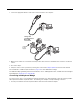
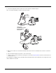
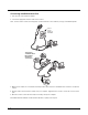

Table Of Contents
- Voyager™ 1200g/1202g/1202g-BF User’s Guide
- Table of Contents
- Getting Started
- Programming the Interface
- Introduction
- Programming the Interface - Plug and Play
- USB Serial Commands
- Verifone® Ruby Terminal Default Settings
- Gilbarco® Terminal Default Settings
- Honeywell Bioptic Aux Port Configuration
- Datalogic™ Magellan© Bioptic Aux Port Configuration
- NCR Bioptic Aux Port Configuration
- Wincor Nixdorf Terminal Default Settings
- Wincor Nixdorf Beetle™ Terminal Default Settings
- Wincor Nixdorf RS232 Mode A
- Keyboard Country Layout
- Keyboard Wedge Modifiers
- RS232 Modifiers
- NCR Modifiers
- Scanner to Bioptic Communication
- Cordless System Operation (Voyager 1202g)
- How the Charge and Communications Base Works
- Linking the Scanner to a Base
- Communication Between the Cordless System and the Host
- RF (Radio Frequency) Module Operation
- System Conditions
- Page Button
- About the Battery
- Voyager 1202g Battery Removal
- Flash Updates
- Beeper and LED Sequences and Meaning
- Reset Scanner
- Scanning While in Base Cradle
- Base Charging Modes
- Paging
- Scanner Address
- Base Address
- Scanner Modes
- Unlinking the Scanner
- Override Locked Scanner
- Out-of-Range Alarm
- Scanner Power Time-Out Timer
- RangeGate
- Batch Mode
- Scanner Name
- Using the Scanner with Bluetooth Devices
- Minimizing Bluetooth/ISM Band Network Activity
- Reset Scanner and Base
- Cordless System Operation (Voyager 1202g-BF)
- How the Charge and Communications Base Works
- Linking the Scanner to a Base
- Communication Between the Cordless System and the Host
- RF (Radio Frequency) Module Operation
- System Conditions
- About the Instant Charge Pack
- Flash Updates
- Beeper and LED Sequences and Meaning
- Reset Scanner
- Scanning While in Base Cradle
- Paging
- Scanner Address
- Base Address
- Scanner Modes
- Unlinking the Scanner
- Override Locked Scanner
- Out-of-Range Alarm
- Using the Scanner with Bluetooth Devices
- Minimizing Bluetooth/ISM Band Network Activity
- Reset Scanner and Base
- Input/Output Settings
- Data Editing
- Data Formatting
- Symbologies
- All Symbologies
- Message Length Description
- Codabar
- Code 39
- Interleaved 2 of 5
- NEC 2 of 5
- Code 93
- Straight 2 of 5 Industrial (three-bar start/stop)
- Straight 2 of 5 IATA (two-bar start/stop)
- Matrix 2 of 5
- Code 11
- Code 128
- GS1-128
- Telepen
- UPC-A
- UPC-A/EAN-13 with Extended Coupon Code
- UPC-E0
- EAN/JAN-13
- EAN/JAN-8
- MSI
- Plessey Code
- GS1 DataBar Omnidirectional
- GS1 DataBar Limited
- GS1 DataBar Expanded
- Trioptic Code
- GS1 Emulation
- Postal Codes
- Utilities
- Serial Programming Commands
- Product Specifications
- Maintenance and Troubleshooting
- Reference Charts

1 - 4
Connecting with RS232 Serial Port
1. Turn off power to the terminal/computer.
2. Connect the appropriate interface cable to the scanner.
Note: For the scanner or base to work properly, you must have the correct cable for your type of terminal/computer.
3. Make sure the cables are secured in the wireways in the bottom of the base and that the base sits flat on a horizontal
surface.
4. Plug the serial connector into the serial port on your computer. Tighten the two screws to secure the connector to the
port.
5. Once the scanner or base has been fully connected, power up the computer.
The RS232 Serial Port defaults to 9600 baud, 8 data bits, no parity, and 1 stop bit.
only if
power
supply is
included
Charge and
Communications
Base RS232
Serial Port
Connection: