MS9500 Voyager™ Series Single-Line Hand Held Laser Scanner User's Guide
Disclaimer Honeywell International Inc. (“HII”) reserves the right to make changes in specifications and other information contained in this document without prior notice, and the reader should in all cases consult HII to determine whether any such changes have been made. The information in this publication does not represent a commitment on the part of HII.
TABLE OF CONTENTS Introduction Product Overview ............................................................................................. 1 Scanner and Accessories ................................................................................. 2 Scanner Components ....................................................................................... 4 The PowerLink Cable Disconnecting ............................................................................................... 5 Connecting ........
TABLE OF CONTENTS IR Activation Range............................................................................................ 25 Applications and Protocols ................................................................................. 26 Troubleshooting Guide ....................................................................................... 27 Design Specifications Operational ..................................................................................................... 30 Mechanical ....
INTRODUCTION Product Overview Honeywell’s MS9500 Voyager™ series of hand-held (single-line) laser scanners offers the user an aggressive solution for scanning all standard 1D bar codes including GS1 DataBar™ (RSS) bar codes. The MS9500 series is equipped with both in-stand and out-of-stand operation enabling hand-held or fixed projection scanning. The MS9520 Voyager model includes all of the same features as the MS9540 VoyagerCG™ model, with the exception of Honeywell’s patented CodeGate™ technology.
INTRODUCTION Scanner and Accessories BASIC KIT Part # Description MS9520 or MS9540 Voyager Bar Code Scanner or VoyagerCG Bar Code Scanner with CodeGate 00-02544 MetroSelect Single-Line Configuration Guide* 00-02410 MS9500 Voyager Series Single-Line Hand Held Laser Scanner User’s Guide* * Available for download at - www.honeywellaidc.com OPTIONAL ACCESSORIES Part # Description AC to DC Power Transformer - Regulated 5.2VDC @ 1A output.
INTRODUCTION Scanner and Accessories OPTIONAL ACCESSORIES Part # 53-53213x-N-3 53-53214x-N-3 Description USB Full Speed Cable Locking Plus-Power™ Type A, Black, Coiled Cord with Long Strain Relief USB Full Speed Cable Locking Plus-Power™ Type A, Black, Coiled Cord with Long Strain Relief, Extended Length Not for use with Low Speed USB scanners. Use with Full Speed USB scanners only.
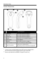
INTRODUCTION Scanner Components No. Item Description ♦ 1 Green LED 2 Red LED 3 ♦ See Visual Indicators on page 18 See Visual Indicators on page 18 ♦♦ Yellow LED ♦♦ See Visual Indicators on page 18 4 Button See How to use CodeGate on page 12 5 Red Window Laser Aperture 6 Speaker See Audible Indicators on page 17 7 Cable Release Pin-Hole See The PowerLink Cable on page 5 8 Cable Connection 10-pin RJ45, Female Socket, See Scanner Pinout Connections on page 32 Figure 1.
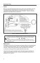
INTRODUCTION Disconnecting the PowerLink Cable Before removing the cable from the scanner, Honeywell recommends that the power on the host system is off and the power supply has been disconnected from the PowerLink cable. Figure 2. 1. Locate the small ‘pin-hole’ on the top of the unit near the bottom of the scanner. 2. Bend an ordinary paperclip into the shape shown above. 3. Insert the paperclip (or other small metallic pin) into the small ‘pin-hole’. 4.
INTRODUCTION Labels Every scanner has labels and molded text located on the underside of the unit. The labels and text contain important information such as the unit’s date of manufacture, serial number, CE and caution information. Figure 5 provides examples of the labels and the molded text. Figure 5 .
INSTALLING THE SCANNER TO THE HOST SYSTEM RS232, Laser Emulation, and Light Pen Emulation 1. Turn off the host system. 2. Connect the 10-pin RJ45 male connector into the jack on the scanner. There will be an audible click when the connector lock engages. If the scanner is receiving power from the host system, skip to step #5. 3. Connect the L-shaped plug of the power supply into the power jack on the PowerLink cable. 4. Verify the AC input requirements of the power supply match the AC outlet.
INSTALLING THE SCANNER TO THE HOST SYSTEM RS485 1. Turn off the host system. 2. Plug the male 10-pin RJ45 end of the MVC cable into the 10-pin socket on the scanner. There will be an audible click when the connection is made. 3. Connect the other end of the MVC cable to the host device. 4. Turn on the host system. Figure 7. Plugging the scanner into a port on the host system does not guarantee that scanned information will be communicated properly to the host system.
INSTALLING THE SCANNER TO THE HOST SYSTEM Keyboard Wedge 1. Turn off the host system. 2. Connect the 10-pin RJ45 male connector into the jack on the scanner. There will be an audible click when the connection is made. If the scanner is receiving power from the host system, skip to step #5. 3. Connect the L-shaped plug of the power supply into the power jack on the PowerLink cable. 4. Verify the AC input requirements of the power supply match the AC outlet. Connect the power supply into an AC outlet.
INSTALLING THE SCANNER TO THE HOST SYSTEM Stand-Alone Keyboard 1. Turn off the host system. 2. Connect the 10-pin RJ45 male connector into the jack on the scanner. There will be an audible click when the connection is made. If the scanner is receiving power from the host system, skip to step #5. 3. Connect the L-shaped plug of the power supply into the power jack on the PowerLink cable. 4. Verify the AC input requirements of the power supply match the AC outlet.
INSTALLING THE SCANNER TO THE HOST SYSTEM Integrated USB: Full Speed (-40) Low Speed (-38) 1. Turn off the host system. 2. Connect the 10-pin RJ45 male connector of the USB cable into the jack on the scanner. There will be an audible click when the connection is made. 3. Connect the other end of the USB cable to the host USB port. 4. Turn on the host system. Figure 10. As a default, the MS95x0-38 leaves the factory with USB Keyboard Emulation Mode enabled.
THE MS9540 VOYAGERCG SERIES How to Use CodeGate and the Manual Activation Mode CODEGATE MANUAL ACTIVATION MODE* * This feature is not a default setting. Refer to the MetroSelect Configuration Guide for instructions on enabling the Manual Activation Mode. Figure 11. Figure 12.
STAND KITS Types Free Standing Kit #46-46128 (Figure 13) c. a. Kit Contains: a. Stand.......................................................... Qty. 1 b. Apron ......................................................... Qty. 1 c. Screw, M3 x 6 mm ...................................... Qty. 2 d. Washer, #5 x .5 OD .................................... Qty. 2 e. Stand Anchor.............................................. Qty. 1 f. M3 x 20 mm Set Screw............................... Qty. 1 d. b. e. f.
STAND KITS Assembly There are two options for assembling the stand. The first option is a selfsupporting stand that can be moved freely about on the countertop. The second option is used if the stand will be bolted or hard-mounted to the countertop. Stand Option 1: Self-Supported Stand Kit #46-46128 Apron Step 1 Slide the apron over the stand. Stand Figure 17. Step 2 Position the stand so that it sits under the tab on the apron.
STAND KITS Assembly Stand Option 2: Hard-Mount Kits #46-46128 and #46-46351 Anchor from Kit #46-46128 Base Assembly from Kit #46-46351 or MS951 Stand Base Step 3 Screw the stand anchor onto the base assembly until it sits flush. Figure 21. Step 4 Remove the logo plate on the stand by gently using an exacto knife to release the plate hook. Figure 22. Step 5 Position the stand over the base assembly. Figure 23.
STAND KITS Assembly Wall Mount, Option 1: For Kit #46-46508 Step 1 Drill two #39 pilot holes 3.00″ apart. Step 2 Attach the Wall Mount Hanger to the wall with the two #8 wood screws provided. Figure 26. Wall Mount, Option 2: Kit #46-46508 Step 1 Attach the Wall Mount Base to the Wall Mount Hanger with the two 4.8 x 13 mm self-tapping screws. Step 2 Remove one side of the protective backing from the double-sided adhesive tape. Figure 27.
INDICATORS Audible When the Voyager is in operation, it provides audible feedback. These sounds indicate the status of the scanner. Eight settings are available for the tone of the beep (normal, six alternate tones and no tone). To change the beeper tone, refer to the MetroSelect Single-Line Configuration Guide or MetroSet2’s help files. One Beep When the scanner first receives power, the green* LED will turn on, the red* LED will flash, and the scanner will beep once. The scanner is ready to scan.
INDICATORS Visual Figure 29. LED Configuration The MS9540 has three LED indicators located on the head of the scanner. The MS9520 has two LED indicators located on the head of the scanner. When the scanner is in operation, the flashing, or stationary activity of the LEDs indicates the status of the scanner and the current scan. All LEDs are Off The LEDs will not be illuminated if the scanner is not receiving power from the host or transformer. The scanner is in stand-by mode, and CodeGate is enabled.
INDICATORS Failure Modes Razzberry Tone – On Start-Up This indicates the scanner has experienced a flipper/motor failure. Return the unit for repair to an authorized service center. Continuous Razzberry Tone with all LEDs Off If, upon power, the scanner emits a continuous razzberry tone, then the scanner has an experienced an electronic failure. Return the unit for repair to an authorized service center.
CONFIGURATION MODES The MS9500 Voyager has three modes of configuration. • Bar Codes The MS7120 can be configured by scanning the bar codes located in the MetroSelect Single-Line Configuration Guide. This manual is available for download at www.honeywellaidc.com. • MetroSet2 ® This user-friendly Windows -based configuration program allows you to simply ‘point-and-click’ at the desired scanner options. MetroSet2 is available for download at www.honeywellaidc.com.
CONFIGURATION MODES 4. During configuration, the motor and laser turn off. YOU CANNOT SCAN A BAR CODE WHILE IN SERIAL CONFIGURATION MODE. 5. There is a 20 second window between commands. If a 20 second timeout occurs, the scanner will send a [nak] and you must start over. 6. To enter serial configuration mode, send the following command [stx]999999[etx]. 7. To exit serial configuration mode, send the following command [stx]999999[etx], the scanner will respond with an [ack] followed by 3 beeps. 8.
CONFIGURATION MODES EXAMPLE #3: The following example shows the events that occur when an invalid bar code is sent. This sample will load the factory default settings and then set the baud rate to 19200.
UPGRADING THE FIRMWARE The Voyager series is part of Honeywell’s line of scanners with flash upgradeable firmware. The upgrade process requires a new firmware file supplied to the customer by a customer service representative and MetroSet2 software. A personal computer running Windows 95 or greater with an available RS232 serial or USB port is required to complete the upgrade. Do not use the standard cable supplied with Keyboard Wedge or RS485 interface kits for firmware upgrades.
DEPTH OF FIELD MINIMUM BAR CODE ELEMENT WIDTH A B C D E F G H J K mm .13 .15 - - .19 - .25 .33 .53 - mils 5.2 5.7 - - 7.5 - 10 13 21 - Figure 30.
IR ACTIVATION RANGE The scanner's laser will turn off if the scanner has been idle. When the scanner's IR detects movement in the activation area (see figure below), the laser will automatically turn on, preparing the scanner for bar code recognition, decoding, and transmission. The default laser/scan mode for the MS9500 series is normal scan. Figure 31.
APPLICATIONS AND PROTOCOLS The model number on each scanner includes the scanner number and factory default communication protocol.
TROUBLESHOOTING GUIDE The following guide is for reference purposes only. Contact a customer service representative to preserve the limited warranty terms on page 36. Symptoms Possible Causes Solution All Interfaces No power is being supplied to the unit. The unit has no LEDs, beep or laser. No power is being supplied to the unit from host. Check the transformer, the outlet and power strip. Make sure the cable is plugged into the unit. Some host systems cannot supply enough current to power Voyager.
TROUBLESHOOTING GUIDE Symptoms Possible Causes The unit powers up, but does not scan and/or beep. The bar code being scanned does not satisfy the configured criteria for character length lock or minimum length. Solution Verify that the bar code being scanned falls into the configured criteria. The scanner defaults to a minimum of 3 character bar code. The following item is only relevant for TTL RS232 and Serial Emulation USB interfaces.
TROUBLESHOOTING GUIDE Symptoms Possible Causes Solution The following four items are relevant for a Keyboard Wedge interface only. The unit scans but the data is not correct. The unit’s configuration is not correct. Make sure that the proper PC type AT, PS2 or XT is selected. Verify the correct country code and data format is selected. Adjust the intercharacter delay symptom. The unit is transmitting each character twice. The unit’s configuration is not correct.
DESIGN SPECIFICATIONS OPERATIONAL Light Source Visible Laser Diode 650 nm Laser Power: Less than 1 mW (peak) Embedded Laser: Depth of Scan Field: Scan Speed: Scan Pattern: Minimum Bar Width: Infrared Activation: Max Power: 10 mW Wavelength: 650 nm 0 mm - 203 mm (0" - 8") for 0.330 mm (13 mil) bar code at default settings 72 scan lines per second Single scan line 0.127 mm (5.
DESIGN SPECIFICATIONS MECHANICAL Length: 198 mm (7.8") Width: Handle - 45 mm (1.8"), Head - 78 mm (3.1") Depth: 40 mm (1.6") Weight: 149 g (5.25 oz) ELECTRICAL Input Voltage: Power: Current: DC Transformers: 5VDC ± 0.25V Operating = 0.825 W typical Standby = 0.600 W typical Operating = 165 mA @ 5VDC typical Standby = 120 mA @ 5VDC typical Class 2; 5.2V @ 1A For regulatory compliance information see pages 37 – 39.
SCANNER AND CABLE TERMINATIONS Scanner Pinout Connections The MS9520 and MS9540 scanner interfaces terminate to a 10-pin modular jack. The serial number label indicates the interface enabled when the scanner is shipped from the factory.
SCANNER AND CABLE TERMINATIONS Scanner Pinout Connections MS95x0-00 Laser Emulation Pin 1 2 3 4 5 6 7 8 9 10 Function Ground RS232 Transmit Output RS232 Receive Input Flip Sense/Start of Scan Output Proximity Detect/Trigger Emulation Output Scan/Laser Enable Input Reserved Data Out +5VDC Shield Ground MS95x0-14 RS232 Pin 1 2 3 4 5 6 7 8 9 10 Function Ground RS232 Transmit Output RS232 Receive Input RTS Output CTS Input DTR Input Reserved DSR Out +5VDC Shield Ground MS95x0-40 Full Speed USB & MS95x0-38 L
SCANNER AND CABLE TERMINATIONS Cable Connector Configuration (Host End) RS232 PowerLink Cable PN 53-53000x-3 Pin Function 1 Shield Ground 2 TTL RS232 Transmit Output 3 TTL RS232 Receive Input 4 DTR Input/Light Pen Source 5 Signal Ground 6 Light Pen Data (DSR Out for -14 interfaces) 7 CTS Input 8 RTS Output 9 +5VDC 9-Pin Female, D-Type USB Cables 53-53213x-N-3, 53-53214x-N-3 or 53-53235x-N-3 Pin Function PN 1 PC +5V/V_USB 2 D- 3 D+ 4 Ground Shield Shield Locking Type A Non-Lo
SCANNER AND CABLE TERMINATIONS Cable Connector Configuration (Host End) Keyboard Wedge PowerLink Cable PN 53-53002x-3 Pin 1 2 3 4 5 Pin 1 Function Keyboard Clock Keyboard Data No Connect Power Ground +5 Volts DC Function PC Data 2 3 No Connect Power Ground 4 5 6 +5 Volts DC PC Clock No Connect 5-Pin DIN, Female 6-Pin DIN, Male Honeywell will supply an adapter cable with a 5-pin DIN male connector on one end and a 6-pin mini DIN female connector on the other.
LIMITED W ARRANTY Honeywell International Inc. ("HII") warrants its products and optional accessories to be free from defects in materials and workmanship and to conform to HII’s published specifications applicable to the products purchased at the time of shipment.
REGULATORY COMPLIANCE Safety ITE Equipment IEC 60950-1 Second Edition EN 60950-1 Second Edition Laser Laser Class 1: IEC 60825-1: Second Edition 2007 EN 60825-1: Second Edition 2007 Complies with 21 CFR 1040.10 and 1040.11 except for deviations pursuant to Laser Notice No. 50, dated June 24, 2007. LED IEC 62471: Exempt Risk Group Caution Use of controls or adjustments or performance of procedures other than those specified herein may result in hazardous laser light exposure.
REGULATORY COMPLIANCE Attenzione L’utilizzo di sistemi di controllo, di regolazioni o di procedimenti diversi da quelli descritti nel presente Manuale può provocare delle esposizioni a raggi laser rischiose. Il cliente non deve assolutamente tentare di riparare egli stesso lo scanner laser. Non guardate mai il raggio laser, anche se credete che lo scanner non sia attivo. Non aprite mai lo scanner per guardare dentro l’apparecchio. Facendolo potete esporVi ad una esposizione laser rischiosa.
REGULATORY COMPLIANCE Warnung! Dies ist eine Einrichtung der Klasse A. Diese Einrichtung kann im Wohnbereich Funkstörungen verursachen. In diesem Fall kann vom Betreiber verlangt werden, angemessene Massnahmen durchzuführen. Attenzione Questo e’ un prodotto di classe A. Se usato in vicinanza di residenze private potrebbe causare interferenze radio che potrebbero richiedere all’utilizzatore opportune misure. Attention Ce produit est de classe “A”.
INDEX A AC .................................. see power accessories ............................... 2, 3 adapter .......................................... 2 C cable .............................. 2–3, 27–29 adapter....................................... 2 communication.... 1, 2–3, 5, 7–11, 29, 32–35 disconnect.................................. 5 MVC ....................................... 3, 8 pin assignments ................. 32–35 caution ..................................... 6, 37 labels ...............
INDEX S U safety ........................................... 37 SELV ............................ see caution serial number................................. 6 specifications ......................... 30, 31 stand.................................. 3, 13–16 UL ................................. see caution USB ............................ see interface T termination............................. 32–35 troubleshooting ...................... 27–29 V ventilation ....................................
CUSTOMER SUPPORT Technical Assistance If you need assistance installing or troubleshooting your device, please contact us by using one of the methods below: Knowledge Base: www.hsmknowledgebase.com Our Knowledge Base provides thousands of immediate solutions. If the Knowledge Base cannot help, our Technical Support Portal (see below) provides an easy way to report your problem or ask your question. Technical Support Portal: www.hsmsupportportal.
Honeywell Scanning & Mobility 9680 Old Bailes Road Fort Mill, SC 29707 www.honeywellaidc.