
Replacement Part Install Instructions
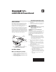

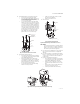
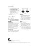
Table Of Contents

40003916 POWERHEAD
3 69-0404—04
5. Install 40003918 Conversion Kit (See Fig. 3).
— Insert new O-ring in the valve body.
— Place metal plate with rubber plug on top
of valve body. Make sure the guide pins on
the underside of metal plate fit into
recesses on valve body.
— Secure the metal plate to the valve body
with the 4 screws (2 sets) provided. One set
of screws has heads with recessed threads
to insert screws for mounting powerhead;
insert this set in the larger screw openings.
The other set has domed heads; insert this
set in the smaller screw openings. Each set
must be inserted in the opposite corners of
the metal plate so screws sit flat on the
plate. Make sure the guide pins on the
plate fit into recesses on valve body.
Fig. 3. Install 4003918 conversion kit.
6. Install new powerhead (Fig. 4).
— Place the manual opening lever (normally
closed models only) on the new powerhead
in the MAN. OPEN position.
— Fit the powerhead onto the valve body,
ensuring that the shaft seats correctly. The
powerhead should be aligned so that the
manual opening lever or slot for lever is at
the port A end of the valve body.
— Secure the powerhead to the valve body
with the 2 screws provided.
— If fitted, reconnect the conduit or cable.
Reconnect the leadwires.
— Replace powerhead cover.
7. Turn on power.
Fig. 4. Install new powerhead.
Systems with new style valve bodies (Series 6)
IMPORTANT
On a new style valve body or a valve body that
has been converted to accept this new power-
head, it is not necessary to drain the system if
the valve body remains in the pipeline.
1. Disconnect power supply before connecting wir-
ing to prevent electrical shock or equipment
damage.
2. Disconnect leadwires to powerhead at terminal
block or conduit connection. Disconnect conduit
or cable connector if fitted. Label each wire for
rewiring later.
3. Remove old powerhead (See Fig. 5).
— Place the manual opening lever (normally
closed models only) on the old powerhead
in the MAN. OPEN position. (Fig. 5A.)
— Remove screw securing the cover to the
powerhead. Lift powerhead cover off. (Fig.
5B.)
— Remove the 2 screws securing the power-
head to the valve body. (Fig. 4.)
— Lift the powerhead off the valve body.
Fig. 5. Remove old powerhead from new style valve body.
A
B
HEX-NUT SCREW
WITH DOMED HEADS (2)
HEX-NUT SCREWS
WITH RECESSED
THREADS AND
SHOULDER SHANK (2)
ADAPTER
PLATE
O RING
LOCATING
RECESSES (3)
VALV E
BODY
M10160
A
B
V
8043F 1036
24V
5
0/60 CY
.32 AMP
@
60 CY
6
SECURING
SCREW (2)
REMOVABLE
HEAD
SHAFT
REMOVABLE HEAD
VALVE BODY ASSEMBLY
M10173
A
A
U
T
O
M
A
N
OP
E
N
MANUAL
OPENING
LEVER
COVER
RETAINING
SCREW
M10161
A
B
B
V8
043F
103
6
24V
50/
60
CY
.
32
AMP
@
60
CY
6
A
B