
Replacement Part Install Instructions
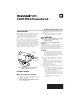


Table Of Contents

40003916 POWERHEAD
© 2020 Resideo Technologies, Inc. All rights reserved.
The Honeywell Home trademark is used under license from Honeywell International, Inc. This product is manufactured by Resideo Technologies, Inc. and its affiliates.
www.resideo.com
Resideo Technologies, Inc.
1985 Douglas Drive North, Golden Valley, MN 55422
1-800-468-1502
69-0404—04 M.S. Rev. 03-20 | Printed in United States
4. Install the new powerhead (See Fig. 4).
— Place the manual opening lever (normally
closed models only) on the new power-
head in the MAN. OPEN position.
— Fit the powerhead onto the valve body,
ensuring that the shaft seats correctly.
The powerhead should be aligned so that
the manual opening lever or slot is at the
port A end of the valve body.
— Secure the powerhead to the valve body
with the 2 screws provided.
— If fitted, reconnect the conduit or cable.
Reconnect the leadwires to the power-
head.
— Replace powerhead cover.
5. Turn on power.
OPERATION AND
CHECKOUT
CAUTION
On 24 V systems, never jumper the valve coil
terminals even temporarily. This may burn
out the heat anticipator in the thermostat.
Operation
Normally closed models
With the manual opening lever set to AUTO and the
powerhead energized, the valve is opened as shown in
Fig. 6A. When the powerhead is de-energized, a
spring-return mechanism drives the valve to the
closed position as shown in Fig. 6B. The valve can
also be opened with no electrical power by moving the
manual opening lever over the stop and pushing
slowly and firmly to the MAN. OPEN position. The
stop permits the valve to be locked in the open
position. The valve will return to automatic position
when the valve is energized.
Auxiliary switch is not energized when valve is
manually opened.
Normally open models
When the powerhead is de-energized, a spring-return
mechanism drives the valve to the open position (Fig.
6A). When energized, the valve is closed as shown in
Fig. 6B. A reverse-acting thermostat is required to
control a normally open valve.
NOTE: Inlet Port is stamped “A”, Outlet Port is
stamped “B” on the valve body.
Fig. 6. Valve.
Checkout
1. Raise the set point on the zone thermostat
above room temperature to initiate a call for
heat.
2. Observe all control devices - the valve should
open and the auxiliary switch should make the
circuit to the circulator or other valve at the end
of the opening stroke.
3. Lower the set point on the zone thermostat
below room temperature.
4. Observe the control devices. The valve should
close and auxiliary equipment should stop.
Service
This valve should be serviced by a trained,
experienced service technician.
1. If the valve is leaking, drain the system and
check to see if the O-ring needs to be replaced.
2. If the gear train is damaged, replace the entire
powerhead assembly. See Installation. If motor
is burned out, replace motor. See Replacement
Parts list in TRADELINE® Catalog.
NOTE: Resideo zone valves are designed and tested
for silent operation in properly designed and
installed systems. However, water noises may
occur as a result of excessive water velocity.
Piping noises may occur in high temperature
(over 212° F [100° C]) systems with insuffi-
cient water pressure.
B
OUT
OPEN POSITION
A
IN
B
OUT
CLOSED POSITION
A
IN
M16955
Fig. 6A.
Fig. 6B.