HZ322 TrueZONE ® Zone Panel Professional Installation Guide 69-2199-03
Installation Guide TABLE OF CONTENTS Specifications...................................................................................................................................1 Accessories......................................................................................................................................1 Mounting...........................................................................................................................................2 Wiring.........................
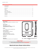
HZ322 TrueZONE APPLICATION The HZ322 TrueZONE panel controls: ® • Conventional gas, oil, or electric forced-air systems up to 2 stages heat and cool; • Heat pump systems with single stage compressor and auxiliary heat, and two stage heat pumps with no auxiliary heat; and two stage heat pumps with no auxiliary heat; • 2 or 3 forced-air zones with wired thermostats, or wireless thermostats using THM4000R wireless adapter.
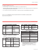
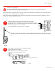
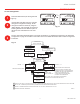
Installation Guide MOUNTING 1 Mount the HZ322 TrueZONE panel near the HVAC equipment; locate it on a wall, stud, roof truss, or cold-air return. NOTE: The HZ322 TrueZONE panel can be mounted in any orientation; level it for appearance only. SPRD BYPASS DAMPER ZD SERIES ZONE DAMPERS SUPPLY DUCT DATS (ALTERNATE LOCATION) TrueZONE PANEL MOUNTED ON RETURN DUCT TrueZONE PANEL MOUNTED ON WALL DATS (AT LEAST 3 FT FROM PLENUM) FURNACE OR AIR CONDITIONER Fig.
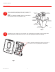
HZ322 TrueZONE WIRING CAUTION: Voltage Hazard. Can cause electrical shock or equipment damage. Disconnect power before beginning installation. Wire entire panel before applying transformer power. Follow these steps for wiring all systems. However, wiring will vary depending on equipment. For conventional systems, refer to page 5. For heat pump systems, see page 6. Wiring must comply with applicable codes, ordinances, and regulations.
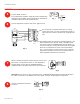
Installation Guide WIRING Fig. 7 M28024 Connect equipment as shown here and on page 5 and 6. HVAC 24 VOLT TRANS. C R W EQUIPMENT W2 FAN RELAY G Y2 Y For oil heat with a separate transformer for cooling, remove this jumper. For other systems leave jumper in place and wire to HVAC R terminal with 18 gauge solid wire. RH RC W1/E W2 Y1 Y2 G O B DS/BK The DS/BK terminal is used with a variable-speed fan.
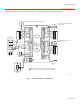
HZ322 TrueZONE CONVENTIONAL The following diagram is an overall view of wiring for a conventional system as depicted in steps 3–8. ARD OR ZD DAMPER SPRING-OPEN POWER-CLOSED M1 COMMON RRD OR MARD DAMPER POWER-OPEN POWER-CLOSED C THERMOSTAT HVAC 24 VOLT TRANS.
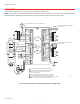
Installation Guide HEAT PUMP Use the following diagram for wiring a heat pump with electric auxiliary heat. NOTE: You can use a conventional thermostat for a heat pump system; however, em heat can only be controlled by heat pump thermostats. The diagram below shows a heat pump thermostat used with a heat pump system. ARD OR ZD DAMPER SPRING-OPEN POWER-CLOSED M1 COMMON RRD OR MARD DAMPER POWER-OPEN POWER-CLOSED THERMOSTAT 2 G O/B L 24 VOLT TRANS.
HZ322 TrueZONE CONFIGURATION To enter Configuration: WIRELESS 1 2 3 Press the Mode button (the Config LED will light up). BACK Use the Back and Next buttons to navigate through the configuration settings. Scroll through the selection choices by using the "Adjust Setting" Left and Right arrow buttons. Pressing Next enters the selected option for that menu item and advances to the next menu.
Installation Guide CONNECT WIRELESS DEVICES WIRELESS 4 Press the Mode button until the Wireless LED lights up. The TrueZONE must be configured for wireless devices to select Wireless mode. BACK HOME CONFIG CHECK OUT MODE ADJUST SETTING NEXT M28194 Press Next to add devices. While the display alternates the Press Connect and Exit screens, push the Connect button(s) on the wireless device(s). -ORFollow the instructions that came with the wireless device(s). Press Next to exit. Fig.
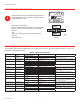
HZ322 TrueZONE OPERATION The HZ322 TrueZONE panel contains an LED display that communicates system and zone status. The LEDs indicate the following information. Much of this information, as well as configuration information, is listed on the label on the inside of the HZ322 cover. For users who prefer French or Spanish labels, they are provided in form 69-2199FS. Cut them out and attach them to the inside of the HZ322 cover. Table 6. LED Operation.
WARRANTY Honeywell warrants the products in this catalog (except those parts designated on Honeywell’s price lists as not covered by this warranty) to be free from defects due to workmanship or materials, under normal use and service, for the following warranty periods. Honeywell VisionPRO®, Commercial VisionPRO , FocusPRO®, PRO 4000, PRO 3000, LineVolt PRO, Digital Round , and Modern Round (T87K, N) Series Thermostats with a date code of 0501 or later: sixty (60) months from date of installation.