
Installation Sheet


HZ432 TrueZONE
13 69-2198—05
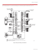
The HZ432 TrueZONE panel contains an LED display that communicates system and
zone status. The LEDs indicate the following information.
OPERATION
M24798
HZ432
HEAT 1
HEAT 2
HEAT 3
COOL 1
COOL 2
PURGE
FAN
EM HEAT
ZONE 1
ZONE 2
ZONE 3
ZONE 4
EMERGENCY
HEAT
Much of this information, as well as configuration information, is listed on the label
on the inside of the HZ432 cover. For users who prefer French or Spanish labels,
they are provided in form 692198FS. Cut them out and attach them to the inside
of the HZ432 cover.
Table 6. LED Operation.
LED Description
HEAT 1 Solid when in heat stage 1. Blinking when DATS high limit mode has been reached.
HEAT 2, 3 Solid when in heat stage 2, 3. Blinking when stage 2, 3 locked out due to DATS or OT.
COOL 1 Solid when in cool stage 1. Blinking when DATS low limit mode has been reached.
COOL 2 Solid when in cool stage 2. Blinking when stage 2 locked out due to DATS.
PURGE Solid when in purge (at power-up and after a call for heat or cool). Blinking when the DATS sen-
sor has failed, or the wires are shorted or open. Will blink for 3 minutes at power-up if DATS is
not present.
FAN Solid with a call for fan.
EM HEAT Solid when in emergency heat mode. This light does not indicate a call for heat. Emergency
heat will only run when both HEAT and EM HEAT are lit.
ZONE 1, 2, 3, 4 Solid green when open or opening. Solid red when closed or closing. Blinking amber when the
VA draw of the dampers exceeds the specified VA, or if there is a short circuit on the damper or
thermostat wiring, causing that zone's breaker to trip.
Fig. 20
To enter Checkout, with the zone panel cover off, press the Mode button until the Check out LED lights up. Use the
Adjust Setting and Next buttons to work through the checkout menu as listed below. See the Configuration section
on page 10 for instructions on using these buttons.
Steps 310 cycle through heating and cooling stages and open and close dampers to verify proper operation of the
equipment and dampers. These steps energize the equipment and damper terminals.
Steps 1114 verify thermostat operation and correct wiring. This is done by making the thermostats call for heat or
cool and viewing the active wires as displayed on the LCD screen. This is a useful way to troubleshoot which ther-
mostat terminals are actually energized on each zone.
Table 7. Checkout.
Checkout Step Line 1 display Line 2 Display Notes:
1. Display shows OT OT SENSOR VAL current OT temp (dynamic) All zone dampers open, all other relays OFF.
2. Display shows DATS DAT SENSOR VAL current DATS (dynamic)
3. Heat stages test TEST HEAT [OFF] 1 2 3 Heat turns on (fan also turns on if configured for
fan on in heat).
4. EM Heat stages test TEST EMERG HEAT [OFF] 1 2 Emergency heat turns on (fan also turns on).
5. Cool stages test TEST COOL [OFF] 1 2 Cooling turns on (fan also turns on).
6. Fan Test TEST FAN [OFF] ON Fan cycles on and off.
7. Damper 1 test TEST Z1 DAMPER [OPEN] CLOSED Cycles damper position with fan on.
8. Damper 2 test TEST Z2 DAMPER [OPEN] CLOSED Cycles damper position with fan on.
9. Damper 3 test TEST Z3 DAMPER [OPEN] CLOSED Cycles damper position with fan on.
10. Damper 4 test TEST Z4 DAMPER [OPEN] CLOSED Cycles damper position with fan on.
11. View Tstat1 inputs ZONE1 STAT INPTS Displays active Tstat1 terminals or displays wireless
thermostat operation
Tests thermostat connection with HVAC off.
12. View Tstat2 inputs ZONE2 STAT INPTS Displays active Tstat2 terminals or displays wireless
thermostat operation
Tests thermostat connection with HVAC off.
13. View Tstat3 inputs ZONE3 STAT INPTS Displays active Tstat3 terminals or displays wireless
thermostat operation
Tests thermostat connection with HVAC off.
14. View Tstat4 inputs ZONE4 STAT INPTS Displays active Tstat4 terminals or displays wireless
thermostat operation
Tests thermostat connection with HVAC off.
15. Exit checkout mode? EXIT CHECKOUT? (NEXT = EXIT)
CHECKOUT