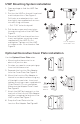
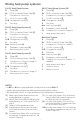
T6 Pro Z-Wave Programmable Thermostat TH6320ZW Professional Install Guide Following Schedule Mode Fan Heat Wake Package Includes: • T6 PRO Z-Wave Thermostat • UWP™ Mounting System • Standard Installation Adapter (J-box adapter) • Decorative Cover Plate – Small; Size 4-49/64 in = 121mm. • Screws and anchors • 3 AA batteries • Professional Install Guide • Getting Started Guide PM Mode Auto Away Home Sleep Menu Fan ProSeries *TH6320ZW2003 depicted. Actual size 4.09'' x 4.09'' x 1.
Read and save these instructions. Introduction The T6 Pro Z-Wave Programmable Thermostat is a Z-Wave Plus certified thermostat capable of controlling up to three heat and two cool stages of heat pump, (incl. dual fuel heat pump systems) and up to two heat and two cool stages of conventional system (3H/2C HP, 2H/2C Conv.) It also measures, displays and reports % indoor relative humidity; however, this model does not control humidification equipment.
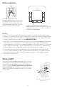
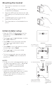
UWP Mounting System installation 1. Open package to find the UWP. See Figure 1. 1 2 2. Position the UWP on the wall. Level and mark hole positions. See Figure 2. Drill holes at marked positions, and then lightly tap supplied wall anchors into wall using a hammer. 3 ‒‒ Drill 7/32” holes for drywall. 4 1/4” 8” to 3/ 3. Pull the door open and insert wires through wiring hole of the UWP. See Figure 3. 4. Place the UWP over the wall anchors. Insert and tighten mounting screws supplied with the UWP.
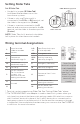
Power options S S Y Y2 G C U U L/A A O/B AUX W2 E W K R Rc Insert R and C wires into designated terminals for primary AC power (C terminal is optional if batteries are installed, but it is recommended). Remove wires by depressing the terminal tabs. Insert 3 AA batteries for primary or backup power. Match the polarity of the batteries with the + / – marks inside the battery compartment. NOTES: • The T6 Pro Z-Wave thermostat works in battery mode or normal power mode based on its power source.
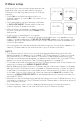
Setting Slider Tabs Set R Slider Tab. UWP Mounting System • Use built-in jumper (R Slider Tab) to differentiate between one or two transformer systems. • If there is only one R wire, and it is connected to the R, Rc, or RH terminal, set the slider to the up position (1 wire). • If there is one wire connected to the R terminal and one wire connected to the Rc terminal, set the slider to the down position (2 wires).
Wiring conventional systems: forced air and hydronics 1H/1C System (1 transformer) R Power [1] Rc [R+Rc joined by Slider Tab] [2] Y Compressor contactor C 24 VAC common [3] W Heat relay G Fan relay 1H/1C System (2 transformers) R Power (heating transformer) [1] Rc Power (cooling transformer) [1] Y Compressor contactor C 24 VAC common [3, 4] W Heat relay G Fan relay Heat-only System R Power [1] Rc [R+Rc joined by Slider Tab] [2] C 24 VAC common [3] W Heat relay Heat-only System with Fan R Power [1] Rc [R+
Wiring heat pump systems 1H/1C Heat Pump System R Power [1] Rc [R+Rc joined by Slider Tab] [2] Y Compressor contactor C 24 VAC common [3] O/B Changeover valve [7] G Fan relay 3H/2C Heat Pump System [10] R Power [1] Rc [R+Rc joined by Slider Tab] [2] Y Compressor contactor (stage 1) C 24 VAC common [3] O/B Changeover valve [7] G Fan relay Aux Auxiliary heat [4] E Emergency heat relay [4] Y2 Compressor contactor (stage 2) L Heat pump fault input 2H/1C Heat Pump System [8] R Power [1] Rc [R+Rc joined by Slid
Mounting thermostat 1 Push excess wire back into the wall opening. 2 Close the UWP door. It should remain closed without bulging. 3 Align the UWP with the thermostat, and push gently until the thermostat snaps in place. 4 If needed, gently pull to remove the thermostat from the UWP. 5 Turn the power on at the breaker box or switch. Initial installer setup • After the T6 Pro Z-Wave thermostat has powered up, touch START SETUP on the thermostat.
Z-Wave setup After you finish the installer setup and set the date and time, you will be asked to set up a Z-Wave to include the thermostat into Z-Wave network. • Touch Yes to include the thermostat in to Z-Wave network, or touch No if you want this to be done later. • You’ll be asked to set your primary controller to INCLUDE MODE. Please refer to the user manual of your Z-Wave controller. • After inclusion procedure has been initiated on your Z-Wave controller, touch Select on the thermostat.
Advanced Z-Wave temperature reporting This thermostat may be configured to report the actual room temperature in a higher resolution than can be shown on the thermostat display. The default temperature reporting resolution is 1 °F or 0.5 °C. When configured to ADVANCED, the temperature reporting resolution will be 0.5 °F or 0.25 °C. To change default temperature reporting to a higher resolution, go to thermostat MENU/Z-WAVE SETUP/TEMP REPORT and set to ADVANCED.
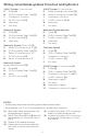
System operation setting 1 Press the Mode button to cycle to the next available System mode. 2 Cycle through the modes until the required System mode is displayed and leave it to activate. AM Following Schedule Mode Fan Heat Auto Away System modes: • Heat: Controls the heating system. • Cool: Controls the cooling system. • Off: Turns the heating and cooling systems off. • Auto: When enabled, the thermostat will automatically use heating or cooling to reach the desired temperature.
Scheduling options This thermostat may be configured to be programmable or non programmable. Thermostat schedule is an optional menu item. It will only show up in the thermostat menu if enabled in the Installer setup – advanced menu. It provides setting for local thermostat schedule control. Once the thermostat is included in to Z-Wave network, it assumes to be programmed from your Z-Wave controller and the program schedule on the thermostat is turned OFF by default.
See table below with default 5+2 schedule (Mon-Fri; Sat-Sun), adjustable settings: Thermostat schedule is turned ON, thermostat included in Z-Wave network Period Start Time Heat (Mon-Fri) Cool (Mon-Fri) Heat (Sat-Sun) Cool (Sat-Sun) Away N/A* 62 ° 85 ° 62 ° 85 ° Home 6:00 Am 70 ° 78 ° 70 ° 78 ° Sleep 10:00 Pm 62 ° 85 ° 62 ° 85 ° *Triggered by Z-Wave controller AM Following Schedule Mode Fan Heat Auto Away Back Home Sleep Sched. On/Off Back Mode Menu Select Back Select Sched.
Key features System status information Cool On, Heat On Auxiliary Heat On, Recovery, or Auto Changeover On. Schedule information Following time or occupancy based temperature control. Desired temperature Displays the desired temperature setting. Indoor temperature/ % indoor relative humidity Touch to display either indoor temperature or % indoor relative humidity. Mode Select system mode: Auto (if enabled)/Heat/ Cool/Off/EM Heat (Emergency Heat if installed and configured).
Heat Stages; Aux/E Stages (#200=Conv.; 200=HP) Fan Control Aux/E Control Aux Heat Type 230 253 255 Equipment Type 205 221 System Type 200 Cool Stages (#200=Conv./ 200=HP) Outdoor Temp 130 220 Temp Scale 125 Reversing Valve Schedule Type 120 218 ISU Name # ISU This option selects the equipment type your thermostat will control. Note: This option is NOT displayed if ISU 200 is set to Cool Only.
Aux Heat Lock Out (Aux Heat Outdoor Lockout) 356 High Heat Stage Finish 306 Balance Point (Compressor Lockout) High Cool Stage Finish 305 355 Auto Differential 303 Up Stage Timer Aux Heat Auto Changeover 300 350 Fossil Kit Control 260 Aux Heat Droop EM Heat Type 256 340 ISU Name # ISU Aux Heat Lockout requires an outdoor temperature. Set Aux Heat Lockout to optimize energy bills and to not allow to run the more expensive Aux Heat source above certain outdoor temperature limit.
ISU Name Cool 1 CPH (Cooling cycle rate stage 1) Cool 2 CPH (Cooling cycle rate stage 2) Heat 1 CPH (Heating cycle rate stage 1) Heat 2 CPH (Heating cycle rate stage 2) Aux Heat CPH (Heating cycle rate Auxiliary Heat) EM Heat CPH (Heating cycle rate Emergency Heat) Compressor Protection Ext Fan Run Time in Cool Ext Fan Run Time in Heat # ISU 365 366 370 371 375 378 387 390 391 This ISU is only displayed when Cool /Compressor Stages is set to 2.
Air Filter 2 Reminder Hum Pad Reminder Dehum Filter Reminder Vent Filter Reminder 712 810 921 1018 Sensor type 515 Air Filter 1 Reminder Indoor Sensor 500 Air Filters Lock Screen 435 711 Maximum Heat Setpoint 431 702 Minimum Cool Setpoint 430 Temperature Control Adaptive Recovery 425 520 ISU Name # ISU 18 Off, 3, 6, 9, 12 months Off 30, 60 Calendar Days 3 - 12 Calendar Months (in 1 month increments) Off 6, 12 Calendar Months Choose either calendar or equipment run time-based
ISU Name UV Devices UV Bulb 1 Reminder UV Bulb 2 Reminder Idle Brightness Clock Format Daylight Saving Temperature Offset Humidity Display Offset # ISU 1100 1105 1106 1401 1410 1415 1420 1425 Set to Off in areas that do not follow Daylight Saving Time. 0 °F - No difference in displayed temperature and the actual room temperature. The thermostat can display up to 3 °F (1.5 C) lower or higher than the actual measured temperature.
Z-Wave configuration parameters If your gateway/hub/controller supports configuration function, you may remotely configure or change the default thermostat configuration parameters. For detailed table with all available Z-Wave configuration parameters go to http://customer.resideo.com or search for T6 Pro Z-Wave Thermostat in the Z-Wave certified products section on http://Z-Wavealliance.org Performing a system test You can test the system setup in ADVANCED MENU under SYSTEM TEST option.
Alerts and reminders Alerts and reminders are displayed via the alert symbol and alert number in the clock area on the home screen. You can read more information about active alerts, snooze or dismiss non-critical alerts in Menu/Alerts. Number Alert/Reminder Definition 54 Thermostat Humidity Sensor Error The sensor of the thermostat has encountered an error. Please contact dealer to replace the thermostat. 164 Heat Pump Needs Service Heat pump needs service.
Alerts and reminders Number Alert/Reminder Definition 252 AC Power Lost If batteries used as backup power it would drain batteries quickly so Z-Wave communication needs to be turned off. The working power mode can only be changed when thermostat is NOT included in a Z-Wave network. Either to exclude and include thermostat back in to Z-Wave network to change the power mode to LSS (power-save, sleep mode) or to resume AC power. You can check the actual power mode in the thermostat MENU/DEVICE INFO.
Specifications Model Number: TH6320ZW2003 Z-Wave Radio: Frequency (USA and Canada): 908.
CAUTION: ELECTRICAL HAZARD Can cause electrical shock or equipment damage. Disconnect power before beginning installation. CAUTION: EQUIPMENT DAMAGE HAZARD Compressor protection is bypassed during testing. To prevent equipment damage, avoid cycling the compressor quickly. CAUTION: MERCURY NOTICE This product should not be disposed of with other household waste. If this product is replacing a control that contains mercury in a sealed tube, do not place the old control in the trash.