
Owner's Manual

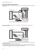


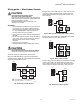
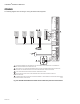
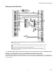

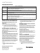
Table Of Contents
- Application
- Features
- Contents
- Specifications
- System Installation
- Installation Options
- Guidelines for Installing RedLINK Devices
- Installing Equipment Interface Module (if used)
- Wiring 24 Vac Common
- Selecting Discharge and Return Air Temperature Sensor Mounting Locations
- Installing Discharge and Return Air Temperature Sensors
- Selecting Thermostat Location
- Installing Wallplate
- Installing VisionPRO® 8000 with RedLINK™
- Wiring the Thermostat
- Remove Coin Cell Battery Tab
- Mounting Thermostat on Wallplate
- Power Optional RedLINK™ Accessories
- Performing Initial Setup
- Installer Tests
- Operation
- Setting the Time/Date
- Setting the Fan
- Setting System Mode
- Adjusting Program Schedules
- Overriding Schedules: Residential Use
- Overriding Schedules: Commercial Use
- Viewing Equipment Status
- Setting Vacation Hold: Residential Use
- Setting Holiday/Event Schedules: Commercial Use
- Setting Custom Events: Commercial Use
- Setting Holiday Schedule: Commercial Use
- Setting Holiday Override: Commercial Use
- Initiating Occupancy Mode: Commercial Use
- Remote Setback: Commercial Use
- Adjusting Humidification Settings
- Adjusting Dehumidification Settings: Residential Use
- Adjusting Dehumidification Settings: Commercial Use
- Adjusting Ventilation Settings
- Ventilation Options
- Setting Preferences
- Cleaning the Thermostat Screen
- Adjusting Security Settings
- Viewing Dealer Information
- Advanced Features
- Installer Options
- Using the Temperature Display
- Using the Humidity Display
- Universal Outputs (U1, U2, U3)
- Universal Inputs (S1, S2, S3, S4)
- Data Logs
- Dry Contact Alerts
- Set Up the Dry Contact Alerts
- Staging Control
- Heat Pump and Backup Heat Operation
- Indoor Air Quality (IAQ) Control
- IAQ Reminders
- Customizable Reminders
- MicroSD card
- Commercial Features
- Overriding Schedules: Commercial Use
- Setting Holiday/Event Schedules: Commercial Use
- Setting Custom Events: Commercial Use
- Setting Holiday Schedule: Commercial Use
- Setting Holiday Override: Commercial Use
- Initiating Occupancy Mode: Commercial Use
- Ramp Rates (Commercial Use)
- Remote Setback (Commercial Use)
- Economizer and Time of Day (TOD) Operation
- Pre-Occupancy Purge
- Battery Replacement
- Optional Accessories
- Portable Comfort Control
- Remote Indoor Sensors
- Replacing a Thermostat
- Replacing an Equipment Interface Module
- Wiring
- Zoning
- Troubleshooting
- Regulatory Information

VISIONPRO
®
8000 WITH REDLINK™
135 68-0312—03
Wiring guide — Wired Indoor Sensors
CAUTION
Electrical Interference (Noise) Hazard.
Can cause erratic system operation.
Keep wiring at least one foot away from large inductive
loads such as motors, line starters, lighting ballasts and
large power distribution panels.
Use shielded cable to reduce interference when
rerouting is not possible.
IMPORTANT
Erratic temperature readings from a sensor can occur
as a result of any of the wiring practices described
below. Avoid these practices to assure correct opera-
tion. Use shielded cable to reduce interference if
rerouting sensor wiring is not possible.
— Be sure wires have a cable separate from the thermo-
stat cable.
— Do not route temperature sensor wiring with building
power wiring, next to control contactors or near light
dimming circuits, electric motors or welding
equipment.
— Avoid poor wiring connections.
— Avoid intermittent or missing building earth ground.
CAUTION
Electrical Shock Hazard.
Can cause electrical shock or equipment damage.
Disconnect power supply before connecting wiring.
Use the S1, S2, S3 or S4 terminals for wired sensors.
Wiring 4 C7189U1005 sensors (10k ohm) for temperature
averaging network. Select 10K in the Installer Setup (ISU 503)
when using C7189U1005 sensor(s).
Fig. 343. Wiring 4 C7189U sensors.
Wiring 2 TR21 sensors (20k ohm) and 1 TR21-A sensor (10k
ohm) for temperature averaging network. Select 20K in the
Installer Setup (ISU 503) when using 2 TR21 sensors and 1
TR21-A sensor.
Fig. 344. Wiring 2 TR21 sensors and 1 TR21-A sensor.
Wiring 4 TR21 sensors (20k ohm). Select 20K in the Installer
Setup (ISU 503) when using TR21 sensor(s).
Fig. 345. Wiring 4 TR21 sensors.
Wiring 2 TR21-A sensors (10k ohm) for temperature averaging
network. Select 20K in the Installer Setup (ISU 503) when
using 2 TR21-A sensors in series. Note: The TR21-A sensor
must be used in combination with TR21 or TR21-A sensor.
Fig. 346. Wiring 2 TR21-A sensors.
C7189
C7189
C7189
C7189
EIM
M31472
THE NUMBER OF C7189U SENSORS MUST BE
A SQUARE NUMBER (1, 4, 9, 16, ETC.)
1
1
M31473
EIM
TR21-A
T3
T4
TR21 TR21
M31474
EIM
TR21 TR21
TR21 TR21
M31475
EIM
TR21-A
T3
T4
TR21-A
T3
T4