
Owner's Manual


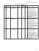


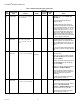
Table Of Contents
- Application
- Features
- Contents
- Specifications
- System Installation
- Installation Options
- Guidelines for Installing RedLINK Devices
- Installing Equipment Interface Module (if used)
- Wiring 24 Vac Common
- Selecting Discharge and Return Air Temperature Sensor Mounting Locations
- Installing Discharge and Return Air Temperature Sensors
- Selecting Thermostat Location
- Installing Wallplate
- Installing VisionPRO® 8000 with RedLINK™
- Wiring the Thermostat
- Remove Coin Cell Battery Tab
- Mounting Thermostat on Wallplate
- Power Optional RedLINK™ Accessories
- Performing Initial Setup
- Installer Tests
- Operation
- Setting the Time/Date
- Setting the Fan
- Setting System Mode
- Adjusting Program Schedules
- Overriding Schedules: Residential Use
- Overriding Schedules: Commercial Use
- Viewing Equipment Status
- Setting Vacation Hold: Residential Use
- Setting Holiday/Event Schedules: Commercial Use
- Setting Custom Events: Commercial Use
- Setting Holiday Schedule: Commercial Use
- Setting Holiday Override: Commercial Use
- Initiating Occupancy Mode: Commercial Use
- Remote Setback: Commercial Use
- Adjusting Humidification Settings
- Adjusting Dehumidification Settings: Residential Use
- Adjusting Dehumidification Settings: Commercial Use
- Adjusting Ventilation Settings
- Ventilation Options
- Setting Preferences
- Cleaning the Thermostat Screen
- Adjusting Security Settings
- Viewing Dealer Information
- Advanced Features
- Installer Options
- Using the Temperature Display
- Using the Humidity Display
- Universal Outputs (U1, U2, U3)
- Universal Inputs (S1, S2, S3, S4)
- Data Logs
- Dry Contact Alerts
- Set Up the Dry Contact Alerts
- Staging Control
- Heat Pump and Backup Heat Operation
- Indoor Air Quality (IAQ) Control
- IAQ Reminders
- Customizable Reminders
- MicroSD card
- Commercial Features
- Overriding Schedules: Commercial Use
- Setting Holiday/Event Schedules: Commercial Use
- Setting Custom Events: Commercial Use
- Setting Holiday Schedule: Commercial Use
- Setting Holiday Override: Commercial Use
- Initiating Occupancy Mode: Commercial Use
- Ramp Rates (Commercial Use)
- Remote Setback (Commercial Use)
- Economizer and Time of Day (TOD) Operation
- Pre-Occupancy Purge
- Battery Replacement
- Optional Accessories
- Portable Comfort Control
- Remote Indoor Sensors
- Replacing a Thermostat
- Replacing an Equipment Interface Module
- Wiring
- Zoning
- Troubleshooting
- Regulatory Information

VISIONPRO
®
8000 WITH REDLINK™
68-0312—03 22
205 Geo Forced Air
None
Cooling Only
Heating and Cooling
Heating and
Cooling
Both No This thermostat has the capability of
controlling Geothermal Radiant Heat,
Geothermal Forced Air and Backup Heat.
If this thermostat is not controlling the
Geothermal Forced Air System, select None.
This setting is typically used if the thermostat
is only controlling Geothermal Radiant Heat.
If this thermostat is using the Geothermal
Forced Air System for cooling and not for
heating, select Cooling Only.
If this thermostat is using the Geothermal
Forced Air System for both heating and
cooling, select Heating and Cooling.
206 Reversing Valve
O (O/B on Cool)
B (O/B on Heat)
O/B on Cool Both No Only displayed if the equipment type is Air to
Air Heat Pump, Geothermal or Geothermal
Radiant.
207 Cool Stages /
Compressor
Stages
1-4
1 if ISU 101 is
Residential
2 if ISU 101 is
Commercial
Both No Conventional:
Cool Stage 3 and 4 are only available if ISU
101 is Commercial.
Cool Stage 3 and 4 must be wired to a
universal terminal (U1, U2 or U3).
Heat Pumps:
Maximum of 2 Compressor Stages for heat
pump systems.
202,
207
Heat Stages /
Backup Heat
Stages
1 - 3
Default is 1
stage if ISU
101 Application
is Residential
Default is 2
stages if ISU
101 Application
is Commercial
Both No Maximum of 3 Heat Stages for conventional
systems.
Maximum of 2 Backup Heat Stages for
systems with more than 1 heating equipment
type.
208 Cool Stage 3
None
U1
U2
U3
Default varies
based on
previous
selections
Commercial No Cool Stage 3 is only available if ISU 1010 is
Commercial.
Cool Stage 3 must be wired to a universal
terminal (U1, U2 or U3).
U1, U2 and U3 are normally open dry contacts
when configured for a stage of Cool. U1, U2
and U3 require power from a system
transformer or a separate transformer.
U2 and U3 are only available on the
Equipment Interface Module (EIM).
Table 2. Installer Setup (ISU) Table. (Continued)
ISU
Number
Installer Setup
Name Settings Default
Residential,
Commercial
or Both
Requires
EIM Notes