
Owner's Manual


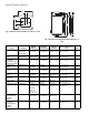
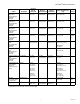


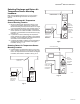

Table Of Contents
- Application
- Features
- Contents
- Specifications
- System Installation
- Installation Options
- Guidelines for Installing RedLINK Devices
- Installing Equipment Interface Module (if used)
- Wiring 24 Vac Common
- Selecting Discharge and Return Air Temperature Sensor Mounting Locations
- Installing Discharge and Return Air Temperature Sensors
- Selecting Thermostat Location
- Installing Wallplate
- Installing VisionPRO® 8000 with RedLINK™
- Wiring the Thermostat
- Remove Coin Cell Battery Tab
- Mounting Thermostat on Wallplate
- Power Optional RedLINK™ Accessories
- Performing Initial Setup
- Installer Tests
- Operation
- Setting the Time/Date
- Setting the Fan
- Setting System Mode
- Adjusting Program Schedules
- Overriding Schedules: Residential Use
- Overriding Schedules: Commercial Use
- Viewing Equipment Status
- Setting Vacation Hold: Residential Use
- Setting Holiday/Event Schedules: Commercial Use
- Setting Custom Events: Commercial Use
- Setting Holiday Schedule: Commercial Use
- Setting Holiday Override: Commercial Use
- Initiating Occupancy Mode: Commercial Use
- Remote Setback: Commercial Use
- Adjusting Humidification Settings
- Adjusting Dehumidification Settings: Residential Use
- Adjusting Dehumidification Settings: Commercial Use
- Adjusting Ventilation Settings
- Ventilation Options
- Setting Preferences
- Cleaning the Thermostat Screen
- Adjusting Security Settings
- Viewing Dealer Information
- Advanced Features
- Installer Options
- Using the Temperature Display
- Using the Humidity Display
- Universal Outputs (U1, U2, U3)
- Universal Inputs (S1, S2, S3, S4)
- Data Logs
- Dry Contact Alerts
- Set Up the Dry Contact Alerts
- Staging Control
- Heat Pump and Backup Heat Operation
- Indoor Air Quality (IAQ) Control
- IAQ Reminders
- Customizable Reminders
- MicroSD card
- Commercial Features
- Overriding Schedules: Commercial Use
- Setting Holiday/Event Schedules: Commercial Use
- Setting Custom Events: Commercial Use
- Setting Holiday Schedule: Commercial Use
- Setting Holiday Override: Commercial Use
- Initiating Occupancy Mode: Commercial Use
- Ramp Rates (Commercial Use)
- Remote Setback (Commercial Use)
- Economizer and Time of Day (TOD) Operation
- Pre-Occupancy Purge
- Battery Replacement
- Optional Accessories
- Portable Comfort Control
- Remote Indoor Sensors
- Replacing a Thermostat
- Replacing an Equipment Interface Module
- Wiring
- Zoning
- Troubleshooting
- Regulatory Information

VISIONPRO
®
8000 WITH REDLINK™
3 68-0312—03
SPECIFICATIONS
Thermostat Description:
Electrical Ratings for: the Equipment Interface Module and
VisionPRO Thermostats
NOTE: To find what terminals are available on the Equip-
ment Interface Module and the VisionPRO Thermo-
stats, see "Terminal Designations" below the table.
Terminal Designations:
— Equipment Interface Module: R, RC, RH, C, W-O/B,
W2-AUX 1, W3-AUX 2, Y, Y2, G, A-L/A, U1 U1, U2 U2,
U3 U3, S1 S1, S2 S2, S3 S3, S4 S4, A, B, C, D
— TH8321 Thermostat: R, RC, C, W-O/B, W2-AUX/E, Y, Y2,
G, A-L/A, K, U1 U1, S1 S1
— TH8320 Thermostat: R, RC, C, W-O/B, W2-AUX/E, Y, Y2,
G, A-L/A, K, S1 S1
— TH8110 Thermostat: R, RC, C, W-O/B, Y, G, K, S1 S1
Power Consumption of TH8321/TH8320/TH8110:
Backlight on: 1.44 VA
Backlight off: 1.32 VA
RedLINK Communication:
Frequency: 900 Mhz frequency range
Re-Sync Time: RedLINK devices re-establish communication
within 6 minutes after AC power resumes.
Temperature Setting Range:
Heating: 40 to 90 °F (4.5 to 32 °C).
Cooling: 50 to 99 °F (10 to 37 °C).
Temperature Sensor Accuracy:
± 1.5 F at 70 F (0.75 C at 21.0 C)
Humidification Setting Range:
10% to 60% RH.
Dehumidification Setting Range:
40% to 80% RH.
Humidity Display Range:
0% to 99%.
Humidity Sensor Accuracy:
± 5% RH from 30% to 50% RH at 75 F.
Cool Indication:
VisionPRO® 8000 with RedLINK™ displays “Cool On” when
the thermostat turns the cooling on.
Heat Indication:
VisionPRO® 8000 with RedLINK™ displays “Heat On” when
the thermostat turns the heating on.
Auxiliary Heat Indication:
VisionPRO® 8000 with RedLINK™ displays “Aux Heat On”
when the thermostat turns the auxiliary heat on.
Interstage Differential:
Comfort:
The thermostat keeps the indoor temperature within 1
degree of the setpoint (droop less control). The thermostat
turns on stage 2 when the capacity on stage 1 reaches 90%.
When the interstage differential is set to 1.0 or higher, the ther-
mostat stages the equipment based on how far the indoor
temperature is from the setpoint (ISU 303 to 309). See
page 27 for more information.
Clock Accuracy: 1 minute per month at 77 °F (25 °C). ± 2
minutes per month over the operating ambient temperature
range.
Mounting Means:
Thermostat mounts directly on the wall in the living space
using mounting screws and anchors provided. Fits a hori-
zontal 2 x 4 in. junction box.
Equipment Interface Module (EIM) mounts on HVAC equip-
ment or on a wall in the equipment room.
Fig. 1. Dimensions of thermostat in in. (mm).
Feature Description
Powering method • Common wire or battery
System types (up to
4 heat/2 cool heat
pump and up to 3
heat/2 cool
conventional)
• Gas, oil or electric heat with air
conditioning
• Warm air, hot water, high-efficiency
furnaces, heat pumps, steam and
gravity
• Cool only
Changeover Manual or Auto changeover selectable
System setting Em Heat-Heat-Off-Cool-Auto
Fan setting Auto-On-Circ-Follow Schedule
Terminal
Voltage
(50/60 Hz)
Max. Current
Rating
W - O/B 18 to 30 VAC and
750 mVDC
1.00A
Y (cooling) 18 to 30 VAC 1.00A
G (fan) 18 to 30 VAC 0.50A
W2 - Aux 1 (heating) 18 to 30 VAC 0.60A
W3 - Aux 2 (heating) 18 to 30 VAC 0.60A
Y2 (cooling) 18 to 30 VAC 0.60A
A-L/A (Output) 18 to 30 VAC 1.00A
U1, U1
U2, U2
U3, U3
30 VAC max. 0.50A
M34521
4-15/16 (126)
4-5/8
(118)
1-1/8 (29)
3-5/16 (84)