
Owner's Manual


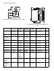
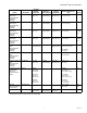


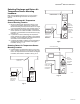

Table Of Contents
- Application
- Features
- Contents
- Specifications
- System Installation
- Installation Options
- Guidelines for Installing RedLINK Devices
- Installing Equipment Interface Module (if used)
- Wiring 24 Vac Common
- Selecting Discharge and Return Air Temperature Sensor Mounting Locations
- Installing Discharge and Return Air Temperature Sensors
- Selecting Thermostat Location
- Installing Wallplate
- Installing VisionPRO® 8000 with RedLINK™
- Wiring the Thermostat
- Remove Coin Cell Battery Tab
- Mounting Thermostat on Wallplate
- Power Optional RedLINK™ Accessories
- Performing Initial Setup
- Installer Tests
- Operation
- Setting the Time/Date
- Setting the Fan
- Setting System Mode
- Adjusting Program Schedules
- Overriding Schedules: Residential Use
- Overriding Schedules: Commercial Use
- Viewing Equipment Status
- Setting Vacation Hold: Residential Use
- Setting Holiday/Event Schedules: Commercial Use
- Setting Custom Events: Commercial Use
- Setting Holiday Schedule: Commercial Use
- Setting Holiday Override: Commercial Use
- Initiating Occupancy Mode: Commercial Use
- Remote Setback: Commercial Use
- Adjusting Humidification Settings
- Adjusting Dehumidification Settings: Residential Use
- Adjusting Dehumidification Settings: Commercial Use
- Adjusting Ventilation Settings
- Ventilation Options
- Setting Preferences
- Cleaning the Thermostat Screen
- Adjusting Security Settings
- Viewing Dealer Information
- Advanced Features
- Installer Options
- Using the Temperature Display
- Using the Humidity Display
- Universal Outputs (U1, U2, U3)
- Universal Inputs (S1, S2, S3, S4)
- Data Logs
- Dry Contact Alerts
- Set Up the Dry Contact Alerts
- Staging Control
- Heat Pump and Backup Heat Operation
- Indoor Air Quality (IAQ) Control
- IAQ Reminders
- Customizable Reminders
- MicroSD card
- Commercial Features
- Overriding Schedules: Commercial Use
- Setting Holiday/Event Schedules: Commercial Use
- Setting Custom Events: Commercial Use
- Setting Holiday Schedule: Commercial Use
- Setting Holiday Override: Commercial Use
- Initiating Occupancy Mode: Commercial Use
- Ramp Rates (Commercial Use)
- Remote Setback (Commercial Use)
- Economizer and Time of Day (TOD) Operation
- Pre-Occupancy Purge
- Battery Replacement
- Optional Accessories
- Portable Comfort Control
- Remote Indoor Sensors
- Replacing a Thermostat
- Replacing an Equipment Interface Module
- Wiring
- Zoning
- Troubleshooting
- Regulatory Information

VISIONPRO
®
8000 WITH REDLINK™
5 68-0312—03
* The YTHM5421R1010 Equipment Interface Module Kit includes 50062329-001 Discharge/Return Air Sensors. Replacement Dis-
charge/Return Air Sensor part number is C7735A1000.
Wired Wall Mount
Indoor Sensor
(20K ohm Negative
Temperature
Coefficient)
TR21 45 to 99 °F
(7 to 37 °C)
5% to 95%
Non-Condensing
-40 to 150 °F
(-40 to 65.5 °C)
4-9/16 x 3 x 7/8
(116 x 76.5 x 22)
White
Wired Wall Mount
Indoor Sensor
(10K ohm Negative
Temperature
Coefficient)
TR21-A 45 to 99 °F
(7 to 37 °C)
5% to 95%
Non-Condensing
-40 to 150 °F
(-40 to 65.5 °C)
4-9/16 x 3 x 7/8
(116 x 76.5 x 22)
White
Wired Flush Mount
Indoor Sensor
(20K ohm Negative
Temperature
Coefficient)
C7772A1004 45 to 99 °F
(7 to 37 °C)
5% to 95%
Non-Condensing
-40 to 150 °F
(-40 to 65.5 °C)
4-1/2 x 2-3/4 x 5/16
(114 x 70 x 8)
Brushed
Stainless
Steel
Wired Flush Mount
Indoor Sensor
(20K ohm Negative
Temperature
Coefficient)
C7772A1012 45 to 99 °F
(7 to 37 °C)
5% to 95%
Non-Condensing
-40 to 150 °F
(-40 to 65.5 °C)
4-1/2 x 2-3/4 x 5/16
(114 x 70 x 8)
Brushed
Stainless
Steel
Discharge or Return Air
Sensor
(10K ohm Negative
Temperature
Coefficient)
C7735A1000
*
0 to 200 °F
(- 17.8 to 93.3 °C)
- - -20 to 120 °F
(-28.9 to 48.9 °C)
Probe:
3-3/4 x 1/4 (77 x 6.4)
Cap Diameter:
2-7/16 (62)
Gray
Discharge or Return Air
Sensor
(20K ohm Negative
Temperature
Coefficient)
C7041 - - - - - - 4-3/16 x 2-5/16 x 1-11/16
(107 x 59 x 43)
- -
Discharge or Return Air
Sensor
(20K ohm Negative
Temperature
Coefficient)
C7770A1006 45 to 99 °F
(7 to 37 °C)
5% to 95%
Non-Condensing
-40 to 150 °F
(-40 to 65.5 °C)
Probe: 6 x 1/4
(152 x 6.4)
- -
Occupancy Sensor for
Remote Setback
(Requires an
Equipment Interface
Module)
WSK-24 Receiver:
- 5 to 140 °F
(-21 to 60 °C)
Door Sensor:
-4 to 140 °F
(-20 to 60 °C)
PIR Sensor:
-4 to 104 °F
(-20 to 40 °C)
- - - - Receiver:
3.6 x 3.4 x 1.2
(91.4 x 86.4 x 30.5)
Door Sensor:
1.4 x 2.3 x 0.6
(35.8 x 57.6 x 15.2)
PIR Sensor:
2.8 x 3.9 x 1.1
(71 x 100 x 28)
White
Coverplate
(covers marks left by
old thermostats)
THP2400A1019 - - - - - - 5-3/4 x 6-5/32
(146 x 156)
Arctic
White
Wire Saver Module THP9045A1023 -40 to 163 °F
(-40 to 73 °C)
5% to 90%
Non-Condensing
-40 to 185 °F
(-40 to 85 °C)
- - Gray
Product Part Number
Operating
Ambient
Temperature
Operating
Relative Humidity
Shipping
Temperature
Physical Dimensions in in.
(mm) Color(s)