
Product Overview
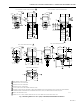
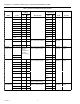
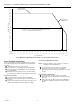
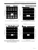
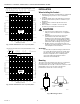
Table Of Contents

V4043A,B,E,J; V4044A,B; V8043A,B,E,F,J; V8044A,B,E MOTORIZED VALVES
60-2133—9
10
Fig. 7. Flow characteristics of 7 C
v
(6.0 kV) valve.
PRESSURE DROP, EQUIVALENT FEET OF PIPE (EQUIVALENT METERS OF PIPE)
2.0
(0.6)
3.0
(0.9)
3.5
(1)
21
(6.4)
24
(7.3)
25
(7.6)
22
(6.7)
23
(7)
20
(6)
19
(5.8)
17
(5.2)
15
(4.6)
13
(4)
10
(3)
-50 (149)
-40 (119)
-30 (89.5)
-20 (60)
(3/4 IN. PIPE)
(1/2 IN. PIPE)
50.0 (345)
10.0 (69)
5.0 (34)
1.0 (7)
0.50 (3.4)
0.10 (0.69)
0.05 (0.34)
0
2
(0.13)
4
(0.25)
6
(0.38)
8
(0.5)
10
(0.63)
12
(0.76)
14
(0.88)
16
(1.0)
18
(1.1)
20
(1.3)
22
(1.4)
24
(1.5)
26
(1.6)
28
(1.8)
30
(1.9)
-0.05 (0.15)
-.1 (0.3)
-.5 (1.5)
-1 (3)
-5 (15)
-10 (30)
M9185A
GAL/MIN (l/s) FLOW RATE
FT OF WATER psi (kPa)
PRESSURE DROP psi (kPa)
7CV
(6.0 KV)
PRESSURE DROP, EQUIVALENT FEET OF PIPE (EQUIVALENT METERS OF PIPE)
2.0
(0.6)
2.5
(0.8)
1.5
(0.5)
19
(5.8)
17
(5.2)
18
(5.5)
15
(4.6)
16
(4.9)
14
(4.3)
10
(3)
12
(3.7)
13
(4)
8
(2.4)
1
(3.4)
9
(2.7)
7
(2.1)
-50 (149)
-40 (119)
-30 (89.5)
-20 (60)
(3/4 IN. PIPE)
(1/2 IN. PIPE)
50.0 (345)
10.0 (69)
5.0 (34)
1.0 (7)
0.50 (3.4)
0.10 (0.69)
0.05 (0.34)
0.01
0
2
(0.13)
4
(0.25)
6
(0.38)
8
(0.5)
10
(0.63)
12
(0.76)
14
(0.88)
16
(1.0)
18
(1.1)
20
(1.3)
22
(1.4)
24
(1.5)
26
(1.6)
28
(1.8)
30
(1.9)
-0.05 (0.15)
-0.1 (0.3)
-0.5 (1.5)
-1 (3)
-5 (15)
-10 (30)
M9186A
GAL/MIN (l/s) FLOW RATE
FT OF WATER psi (kPa) PRESSURE DROP
PRESSURE DROP psi (kPa)
8CV
(6.9 KV)
Fig. 8. Flow characteristics of 8 C
v
(6.9 kV) valve.
INSTALLATION
When Installing this Product…
1. Read these instructions carefully. Failure to follow them
could damage the product or cause a hazardous
condition.
2. Check the ratings given in the instructions and on the
product to make sure the product is suitable for your
application.
3. Installer must be a trained, experienced service
technician.
4. After installation is complete, check out product
operation as provided in these instructions.
CAUTION
1. Disconnect power supply before connecting
wiring to prevent electrical shock or equipment
damage.
2. Normally it is not necessary to remove the
powerhead from the valve body during
installation. If the valve must be disassembled,
be certain that it is reassembled with the water
flow in the direction of the arrow. Reversal of the
powerhead results in damage to the gear train.
3. On 24V systems, never jumper the valve coil
terminals even temporarily. This can burn out the
heat anticipator in the thermostat.
IMPORTANT
Use this valve in hydronic heating systems that do
not contain dissolved oxygen in the system water.
The dissolved oxygen, which is found in systems
that have a frequent source of makeup water,
causes the rubber plug inside the valve to
deteriorate and eventually fail.
Mounting
The valve can be mounted in any position on a vertical line.
See Fig. 9. If the valve is mounted horizontally; the
powerhead must be even with or above the center line of the
piping. Make sure to leave enough room above the
powerhead to remove the cover for servicing.
M10162
VERTICAL
PIPING
HORIZONTIAL
PIPING
Fig. 9. Mounting positions.