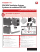
ERV/HRV Ventilation Systems Systèmes de ventilation VRÉ/VRC PROFESSIONAL INSTALLATION GUIDE. GUIDE D’INSTALLATION PROFESSIONNELLE. INCLUDED IN THIS BOX A1 A2 B C D1 D2 A3 E G1 G4 F G2 G5 G6 G3 G7 G8 OPTIONAL CONTROLS SOLD SEPARATELY Tools required to install ERV/HRV Aluminum foil tape (UL181B) Standard screwdriver Crescent wrench Hex driver (1/4 in.) Accessories (not included) 6 in. Dia. insulated duct (VNT5150, VNT5200, VNT6150 & VNT6200) 6 in. Dia. duct (VNT5150, VNT5200) Two 6 in. Dia.
Installation Checklist Liste de vérification pour l’installation Included in This Box A1 ERV/HRV VNT5150H1000, VNT5150E1000 or VNT6150H1000 A2 ERV/HRV VNT5200H1000, VNT5200E1000 or VNT6200H1000 A3 ERV/HRV VNT5070H1000 or VNT5070E1000 B Heat/Energy Recovery Core C Filter (2) D1 Round Duct Collars (4) [VNT5150, VNT5200, VNT6150, VNT6200] D2 Oval Duct Collars (VNT5070) E Installation Kit F Wall Mount Bracket (VNT5070) G Optional controls (sold seperately) Contenu A1 VRE/VRC VNT5150H1000, VNT5150E1000 ou VNT
ERV/HRV Balanced Ventilation Systems ABOUT THE ERV/HRV VENTILATION SYSTEM MAINTAINENCE Benefits.............................................................................................2 Maintenance................................................................................33 Determining Your Ventilation Needs..................................3 Cleaning Steps............................................................................34 Specifications.............................................
About the ERV/HRV Ventilation System The ERV/HRV Balanced Ventilation System provides improved indoor air quality through its high performance and efficiency. Benefits • • • • • • • Ventilation with sensible heat recovery (ERV and HRV) Ventilation with latent heat recovery (ERV only) Simplified mounting (hanging) Optional hanging with included straps.
Determining Your Ventilation Needs How much fresh air do you need? Good air quality is based in part on the capacity of the home’s ventilation system. Usually, the unit’s capacity is measured in CFM (Cubic Feet per Minute) or L/s (Liters per second) of fresh air being distributed in the living space. Use the ASHRAE 62.2 Ventilation Standard, the Room Count Calculation Method, or the Air Change Per Hour (ACH) Method to determine your ventilation needs. ASHRAE 62.2 Ventilation Standard ASHRAE 62.
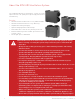
Specifications Dimensions in inches (mm) of VNT5150, VNT5200, VNT6150 and VNT6200 2 1 H 1 FRONT CLEARANCE OF 25 INCHES (635 MM) IS REQUIRED FOR SERVICING UNIT. 2 ALL DUCT CONNECTIONS ARE 6 IN. (150 MM). W L VNT5150H1000, VNT5150E1000 or VNT6150H1000: H = 22 1/2 in. (572 mm), W = 11 1/2 in. (295 mm), L = 29 1/2 in. (749 mm) VNT5200H1000, VNT5200E1000 or VNT6200H1000: H = 22 1/2 in. (572 mm), W = 16 1/2 in. (422 mm), L = 29 1/2 in.
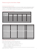
Specifications (continued) VNT5150H1000 Ventilation Performance External Static Pressure Gross Air Flow Net Supply Air Flow Supply Exhaust Pa in. W.C. L/s CFM L/s CFM L/s CFM 25 0.1 91 193 91 194 103 217 50 0.2 84 178 85 179 95 201 75 0.3 77 163 77 163 86 183 100 0.4 71 150 71 151 80 169 125 0.5 63 133 63 134 71 152 150 0.6 57 120 57 121 66 138 175 0.7 51 109 51 109 57 121 200 0.8 46 96 46 96 50 106 225 0.
Specifications (continued) VNT5200H1000 Ventilation Performance External Static Pressure Gross Air Flow Net Supply Air Flow Supply Exhaust Pa in. W.C. L/s CFM L/s CFM L/s CFM 25 0.1 117 248 118 250 130 277 50 0.2 108 229 109 231 119 253 75 0.3 102 218 103 220 110 234 100 0.4 94 200 95 202 101 216 125 0.5 85 181 86 183 92 197 150 0.6 77 163 78 165 82 175 175 0.7 69 146 70 148 71 151 200 0.8 61 129 61 131 60 128 225 0.
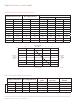
Specifications (continued) VNT5150E1000 Ventilation Performance External Static Pressure Gross Air Flow Net Supply Air Flow Supply Exhaust Pa in. W.C. L/s CFM L/s CFM L/s CFM 25 0.1 97 207 99 210 99 211 50 0.2 89 189 91 193 91 193 75 0.3 88 187 84 179 84 178 100 0.4 75 159 76 162 76 162 125 0.5 70 148 71 150 69 147 150 0.6 62 131 63 133 62 131 175 0.7 55 116 55 118 55 117 200 0.8 49 104 50 106 48 102 225 0.
Specifications (continued) VNT5200E1000 Ventilation Performance External Static Pressure Gross Air Flow Net Supply Air Flow Supply Exhaust Pa in. W.C. L/s CFM L/s CFM L/s CFM 25 0.1 115 244 116 247 108 230 50 0.2 106 225 107 228 101 215 75 0.3 98 208 99 210 95 202 100 0.4 88 188 89 190 83 177 125 0.5 81 173 82 175 74 157 150 0.6 71 150 71 152 67 142 175 0.7 65 139 66 140 60 127 200 0.8 57 122 58 124 52 110 225 0.
Specifications (continued) VNT5070H1000 Ventilation Performance External Static Pressure Gross Air Flow Net Supply Air Flow Supply Exhaust Pa in. W.C. L/s CFM L/s CFM L/s CFM 25 0.1 47 99 48 100 48 102 50 0.2 44 93 45 94 43 92 75 0.3 39 83 40 84 38 80 100 0.4 35 75 35 75 36 78 125 0.5 30 65 30 66 32 68 150 0.6 27 56 27 57 25 52 175 0.7 22 46 22 47 19 41 VNT5070H1000 AIR FLOW (L/S) 0.9 0 10 20 30 40 50 60 225 0.8 200 0.
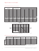
Specifications (continued) VNT5070E1000 Ventilation Performance External Static Pressure Gross Air Flow Net Supply Air Flow Supply Exhaust Pa in. W.C. L/s CFM L/s CFM L/s CFM 25 0.1 49 105 49 105 46 97 50 0.2 46 97 47 99 41 86 75 0.3 44 92 44 93 41 86 100 0.4 37 80 38 81 34 73 125 0.5 34 73 35 74 29 63 150 0.6 29 62 29 63 25 52 175 0.7 23 48 23 49 18 37 200 0.8 22 46 22 47 10 20 VNT5070E1000 AIR FLOW (L/S) 0.
Specifications (continued) VNT6150H1000 Ventilation Performance External Static Pressure Gross Air Flow Net Supply Air Flow Supply Exhaust Pa in. W.C. L/s CFM L/s CFM L/s CFM 25 0.1 72 153 72 153 67 142 50 0.2 67 142 68 143 61 129 75 0.3 61 130 62 130 55 116 100 0.4 55 117 55 118 47 101 125 0.5 49 103 49 103 41 87 150 0.6 42 88 42 89 34 73 175 0.7 35 75 35 75 27 59 200 0.8 28 61 28 61 22 46 VNT6150H1000 AIR FLOW (L/S) 0.
Specifications (continued) VNT6200H1000 Ventilation Performance External Static Pressure Gross Air Flow Net Supply Air Flow Supply Exhaust Pa in. W.C. L/s CFM L/s CFM L/s CFM 25 0.1 122 258 126 260 120 254 50 0.2 114 241 115 242 111 235 75 0.3 105 223 106 225 103 218 100 0.4 98 207 99 209 94 199 125 0.5 89 189 90 190 85 180 150 0.6 81 172 82 174 76 161 175 0.7 72 152 73 154 67 142 200 0.8 63 133 64 135 58 123 225 0.
External Control Options The ERV/HRV unit may be used with one of the following external controls: T10 Pro Smart Thermostat • Controls both heating/cooling and ventilation. • Ventilation programming for time of day or Ashrae standards. • Optional ventilation lockouts for high/low temp or humidity conditions using Internet weather when registered to the app. Prestige™ IAQ Kit • Controls both heating/cooling and ventilation. • Wireless sensor for displaying outdoor temperature and humidity.
Install to Fit Your Application NOTE: Prior to installing, serious consideration must be taken to insure this ventilation system will operate properly if integrated with any other type of mechanical system, i.e. a forced air system, or an air handling unit. To insure proper operation & compatibilities of both system, it is required that the airflows of ventilation systems be balanced, by following the procedures found in this manual. Limitations: The product is for residential applications only.
Install to Fit Your Application (continued) B Exhaust at the Source and Supply in the Return STALE AIR FROM LIVING SPACE, SUCH AS FROM BATHROOM OR KITCHEN TO LIVING SPACE ET 3 FE 6 FE ET 18 INC HE S HRV / ERV FORCED AIR SYSTEM M28984 This application uses a devoted duct system for the exhausting of stale air accumulated in the home. The fresh air is introduced into the return air duct and is distributed through the home by the existing supply air ductwork of the forced air system.
Install to Fit Your Application (continued) C Exhaust and Supply in the Return 6 FEET 3 FEET TO LIVING SPACE 6 FE ET 18 INC HE S FORCED AIR SYSTEM HRV / ERV M28985 When using this application make sure that there is a minimum of 6 feet between the fresh air and exhaust air connections of the ERV/HRV unit in the return air duct. Supply air from the ERV/HRV unit must be at least 3 feet from the forced air system.
Installation Steps 1 Installation Kit Ensure that you have all of the following installation items: 4 Round Duct Collars (VNT5150, VNT5200, Installation Kit: VNT6150 & VNT6200) • 2 Flexible 6 in. Vinyl Ducts (VNT5150, VNT5200, 4 Oval Duct Collars (VNT5070) 2 VNT6150, VNT6200) • 1 Condensation Drain Line (10 in.) • 1 Drain Adapter with Nut • 4 Tie Wraps (30 in.) • 16 Hex-head screws (1/4 x 5/8 in.) • 4 Hex-head screws (1/4 x 1 in.
Installation Steps (continued) 3a Hanging the VNT5150, VNT5200, VNT6150 or VNT6200 The ERV/HRV unit enables you to save time and effort by offering a simplified hanging system. TIP: Removing the core unit makes installation easier since the unit weighs less without the core inside. 1. Attach straps to joist using the supplied washers and four 1 in. hex-head hanging screws. 2. Pull on middle of strap while gently lifting unit upward to raise the unit. 3.
Installation Steps (continued) 3b Mounting the VNT5070 1. Fix the control module bracket to the top of the VNT5070 using the supplied mounting screws. 2. Slide the control module onto the bracket using the key holes. 3. Fix the wall mount bracket to two 2x4s or to a precut sheet of plywood using the supplied mounting screws. 4. Hang the unit on the bracket. 5. Secure with two sheet metal screws.
Installation Steps (continued) 4 Installing the flex duct to the ERV/HRV TIP: Honeywell Home recommends using approximately 16 inches of flexible duct (supplied in kit with VNT5150, VNT5200, VNT6150 and VNT6200) between the unit and the rigid duct for noise dampening. The flex duct is mounted to the unit the same way as the insulated flex. 1. Insert the vinyl duct over the hooks on the duct collar and seal with a supplied 30 inch tie wrap. 3. Finish by taping the duct on the collar.
Installation Steps (continued) 5 Installing the condensation drain line Insert the threaded drain adapter through the bottom of the unit and hand tighten the plastic nut supplied with the drain kit. Use a wrench to tighten the nut another half turn to ensure a complete seal. Install the condensate tubing by pushing the clear plastic tubing over the drain adapter. Make a condensate trap by looping the clear plastic tubing. This loop will prevent foul odors from entering the unit.
Installation Steps (continued) 6 Connecting the power cord ERV/HRV Power Cord Insert the power cord on top of the unit. Press firmly to make sure the power cord is secure. IMPORTANT: Do not plug the power cord into the wall receptacle at this time. Electric Wall Outlet Honeywell Home recommends that the unit has a dedicated receptacle with 120 VAC. Avoid connecting the unit to the wall receptacle with an extension cord. Honeywell Home does not recommend the use of an extension cord.
Installation Steps (continued) 7b Optional Matrix hood (50063805-009) installation for fresh air and exhaust air NOTE: Only for applications up to 115 CFM maximum speed. Higher airflow rates are limited by higher static pressures and the potential of cross-contamination between the supply and exhaust air streams. The Matrix hood design is suitable for smaller spaces commonly found in town homes and condominiums which require less airflow rates. NOTE: A 6 in. to 5 in.
Automated Defrost The ERV and HRV units are equipped with an automatic defrost feature to eliminate any ice build up on the core. • Automatic defrost is initiated once every hour when the fresh air supply temperature drops to 23°F (-5°C) or colder. • The defrost cycle operates by turning off the supply fan while continuing to operate the exhaust fan. • The exhaust fan speed is adjusted proportionally based on the outdoor temperature, initially operating at low speed.
Wiring (continued) Wiring with Remote Controls CONT mode - Ventilator runs continuously on low speed. A ventilation call from a control boosts the ventilator into high speed. INT mode - The ventilator is OFF until a ventilation call from a wall control turns it on in high speed.. Controls Wiring THM5421R (24 VAC) R TO C THERMOSTAT CONV Follow this diagram if using a Prestige™ 2-wire IAQ and RF EIM.
Wiring (continued) TIMER G INTERLOCK RLY1 NC COM NO B G JP1 JP2 D1 LVC – L1 SW2 SW1 SW3 Follow this diagram for General Ventilator Wiring (not interlocked with equipment fan) R Z13 COM PORT THERMOSTAT W B B1 Vectouch CASE GND VENTILATION CONTACTS R G POWERED VENTILATOR REMOTES C Y Y W G W R R G FURNACE 24-VOLT TERMINAL BLOCK ERV/HRV is used in conjunction with a conventional HEAT/COOL thermostat or other wall control.
Wiring (continued) VENT Follow this diagram if using a DG115 IAQ Control. VENT DEHUM DEHUM M28993 Follow this diagram if using a Dehumidistat.
Wiring (continued) B G R Follow this diagram if using the 20/40/60 Minute Boost Control Timer. Note: Multiple timers can be wired in parallel. M28996 Control Panel LED The control panel has a 3-position selector switch and “+” and “–” buttons for speed control. The color of the LED indicator indicates the current function of the selector switch.
Control Panel (continued) Speed Control used as a Mode Control When the LED indicator is green, the selector switch functions as a Mode Selector. The selections are: • INTER (Intermittent): When the selector switch is in the intermittent position the unit will run only when there is a call for ventilation by any external control. At that time the unit will run on high speed until the condition is satisfied.
Balancing Steps (continued) 2 a. Use a pitot tube or flow station to measure the air flow in the fresh air duct and exhaust air duct. (For the VNT5070, make airflow measurements by following the procedure on page 30.) b. Move the mode selector switch to adjust the air flow in the duct with the higher reading. INTER: Exhaust air (right) OFF: Fresh air (left) c. Press the (+) or (–) buttons to adjust the air flow to the desired high speed setting. d.
Balancing Reset NOTE: Once balancing is completed, balancing cannot be changed without resetting the unit. LED To reset: Speed Control 1. Press the (+) and (–) buttons simultaneously for 10 seconds. 2. Indicator light will turn yellow at 5 seconds. 3. Indicator light will turn green at 10 seconds. 4. Release both buttons. 5. Unit has been reset and can be put into balancing mode again.
Airflow Measurements - VNT5070 only (continued) PRESSURE PORT MAGNEHELIC EXHAUST AIR HIGH HIGH LOW LOW FRESH AIR MAGNEHELIC 1 2 32 M33131 Pre & Post Balancing Steps a. Install the flexible duct inner liner (vapor barrier) over the collar and seal with tape, mastic, etc. Note-flexible insulation should be pulled back and away from the duct collar to allow access to pressure ports. b. Proceed with balancing steps described below. c. Plug the pressure ports. d.
Maintenance Quarterly or as Needed 1 Filters. Four times per year or as needed, vacuum the filters. Replace filters as needed. Annually or as Needed 1 2 Inside the Unit. Once a year or as needed, clean the interior of the unit (walls and drain pan) with a mild and non abrasive soap. It is recommended to use products that are environmentally-friendly. Energy Recovery Core Unit (VNT5070E1000, VNT5150E1000 and VNT5200E1000) ERV core: Vacuum the ERV core or rinse with cold water.
Cleaning Steps 1. Disconnect the AC power from the unit or the wall. 3. Clean inside of unit with a damp cloth and wipe dry when finished. 34 2. Open the side door panel by opening the two latches on the top of the side panel and lowering the panel to its fully open position Remove both filters from the top left and right sides of the Core, then vacuum both filters. Slide out the Core, and clean according to the instructions on the previous page. 4.
Troubleshooting CAUTION: Servicing the ERV/HRV unit with its electrical circuitry can cause personal injury. Always make sure that power to the unit is disconnected prior to making any connections. Failure to disconnect the power could result in electrical shock. Service should only be performed by a qualified service technician. Problem Possible Cause or Symptom Test Procedure Solution • • • • • • No Power to Unit HRV/ERV does not turn on. Speed Control green LED light does not come on.
Troubleshooting (continued) Problem Possible Cause or Symptom Test Procedure Solution • • Dehumidistat of the wall controls activated. T-3 Timer 20/40/60 mins. activated. Short circuit between G & R terminals of REMOTES on Speed Control™. Faulty wire between control and H/ERV. Faulty wall control. • • Failure to the HVC or LVC PCB board. Wire connection or wire sequence not corresponding to wiring diagram.
Troubleshooting (continued) Problem Possible Cause or Symptom Test Procedure • • Wiring of fans incorrect on HVC Controller Unit is in its automatic defrost sequence when defrost thermister measures temperature of -5ºC/23ºF • T-3 timer wires connections do not correspond to the Speed Control™. (G & B connections are inverted) HRV/ERV does not operate or respond. • • • Exhaust Fan activated Supply Fan off. • T-3 Timers not • functioning, the LED remains on with a dim green light.
OS and Parts List OS List OS Number Controls Ventilator Type VNT5070H1000 No HRV VNT5070E1000 No ERV VNT5150H1000 No HRV VNT5150E1000 No ERV VNT5200H1000 No HRV VNT5200E1000 No ERV VNT6150H1000 No HRV VNT6200H1000 No HRV Parts List (see illustration on page 39 or page 40 for figure number references) Fig.
Parts Illustration (VNT5150, VNT5200, VNT6150 & VNT6200) See the Parts List table on page 38 for items referenced by figure numbers 1 through 16 in the exploded illustration below.
Parts Illustration (VNT5070) See the Parts List table on page 38 for items referenced by figure numbers 1 through 11 in the exploded illustration below (VNT5150 and VNT5200).
5-Year Limited Warranty Resideo warrants this product to be free from defects in workmanship or materials, under normal use and service, for a period of five (5) years from the date of first purchase by the original purchaser. If at any time during the warranty period the product is determined to be defective due to workmanship or materials, Resideo shall repair or replace it (at Resideo’s option).
42 ERV/HRV Ventilation Systems 69-2480EF—19
Systèmes de ventilation équilibrée VRE/VRC À PROPOS DU SYSTÈME DE VENTILATION VRE/VRC ENTRETIEN Avantages......................................................................................44 Entretien........................................................................................74 Évaluez vos besoins en matière de ventilation..........45 Nettoyage......................................................................................75 Caractéristiques.......................................
À propos du système de ventilation VRE/VRC Le système de ventilation équilibrée améliore la qualité de l’air intérieur grâce à sa haute performance et son efficacité.
Évaluez vos besoins en matière de ventilation De quelle quantité d’air frais avez-vous besoin? Une bonne qualité d’air dépend en partie de la capacité du système de ventilation de la maison. On mesure habituellement la capacité d’un appareil en pi3/min (pieds cubes par minute) ou en l/s (litres par seconde) d’air frais redistribué dans les espaces habités. Utilisez la norme de ventilation résidentielle ASHRAE 62.
Caractéristiques Dimensions en mm (pouces) du VNT5150, VNT5200, VNT6150 et VNT6200: 2 1 1 UN DÉGAGEMENT DE 635 MM (25 PO) EST NÉCESSAIRE DEVANT L’APPAREIL POUR SON ENTRETIEN. 2 TOUS LES RACCORDS DE CONDUIT ONT UN DIAMÈTRE DE 150 MM (6 PO).
Caractéristiques (suite) Performance du VNT5150H1000 en matière de ventilation Pression statique externe Débit d’air brut Débit d’air fourni net Débit d’air fourni Sortie Pa po c.e.
Caractéristiques (suite) Performance du VNT5200H1000 en matière de ventilation Pression statique externe Débit d’air brut Débit d’air fourni net Débit d’air fourni Sortie Pa po c.e.
Caractéristiques (suite) Performance du VNT5150E1000 en matière de ventilation Pression statique externe Débit d’air brut Débit d’air fourni net Débit d’air fourni Sortie Pa po c.e.
Caractéristiques (suite) Performance du VNT5200E1000 en matière de ventilation Pression statique externe Débit d’air brut Débit d’air fourni net Débit d’air fourni Sortie Pa po c.e.
Caractéristiques (suite) Performance du VNT5070H1000 en matière de ventilation Pression statique externe Débit d’air brut Débit d’air fourni net Débit d’air fourni Sortie Pa po c.e. l/s pi /min l/s pi /min l/s pi3/min 25 0,1 47 99 48 100 48 102 50 0,2 44 93 45 94 43 92 75 0,3 39 83 40 84 38 80 100 0,4 35 75 35 75 36 78 125 0,5 30 65 30 66 32 68 150 0,6 27 56 27 57 25 52 175 0,7 22 46 22 47 19 41 3 3 VNT5070H1000 DÉBIT D’AIR (l/s) 0.
Caractéristiques (suite) Performance du VNT5070E1000 en matière de ventilation Pression statique externe Débit d’air brut Débit d’air fourni net Débit d’air fourni Sortie Pa po c.e.
Caractéristiques (suite) Performance du VNT6150H1000 en matière de ventilation Pression statique externe Débit d’air brut Débit d’air fourni net Débit d’air fourni Sortie Pa po c.e.
Caractéristiques (suite) Performance du VNT6200H1000 en matière de ventilation Pression statique externe Débit d’air fourni net Débit d’air brut Débit d’air fourni Sortie Pa po c.e. l/s pi /min l/s pi /min l/s pi3/min 25 0.1 122 258 126 260 120 254 50 0.2 114 241 115 242 111 235 75 0.3 105 223 106 225 103 218 100 0.4 98 207 99 209 94 199 125 0.5 89 189 90 190 85 180 150 0.6 81 172 82 174 76 161 175 0.7 72 152 73 154 67 142 200 0.
Commandes externes en option Le VRE/VRC peut être utilisé avec l’une des commandes externes suivantes : Thermostat intelligent T10 Pro • Règle à la fois le chauffage-refroidissement et la ventilation. • Programmation de la ventilation selon l’heure du jour ou les normes Ashrae. • Verrouillages de ventilation en option pour température ou taux d’humidité bas/élevés selon la météo sur Internet lorsque vous êtes inscrit dans l’application.
Installation selon votre utilisation REMARQUE : Avant l’installation du système de ventilation, il est important de s’assurer qu’il fonctionnera adéquatement s’il est intégré à un autre type de système mécanique (p. ex., un système à air pulsé ou un appareil de traitement de l’air). Dans le but d’assurer la compatibilité des systèmes et leur fonctionnement adéquat, leurs débits doivent être équilibrés selon les procédures décrites dans le présent manuel.
Installation selon votre utilisation (suite) B Évacuation dans la conduite d’entrée et apport dans la conduite de retour VRE VICIÉ DES ESPACES HABITÉS (COMME LES SALLES DE BAIN ET LA CUISINE) 1,83 45, 72 cm (18 4 cm 91,4 i) (3 p VERS LES ESPACES HABITÉS m (6 pi) po) VRC / VRE SYSTÈME À AIR PULSÉ MF28984 Cette application est fondée sur l’utilisation d’un système de conduits destiné à l’évacuation de l’air vicié de la maison.
Installation selon votre utilisation (suite) C Évacuation et apport dans la conduite de retour 1,83 m (6 pi) 91,44 cm (3 pi) VERS LES ESPACES HABITÉS 1,83 45, 72 cm (18 m (6 pi) po) VRE SYSTÈME À AIR PULSÉ VRC / VRE MF28985 Si vous choisissez cette configuration, assurez-vous que les raccords des conduits d’air frais et d’air vicié du VRE/VRC au conduit de retour d’air sont situés à au moins 1,83 m (6 pi) l’un de l’autre.
Procédure d’installation 1 Trousse de quincaillerie Assurez-vous d’avoir les articles suivants en main avant d’installer le produit : 4 colliers de conduit ronds (VNT5150, VNT5200, VNT6150 et VNT6200) 4 colliers de conduit ovales (VNT5070) 2 Trousse de quincaillerie : • 2 gaines flexibles en vinyle de 6 po (VNT5150, VNT5200, VNT6150 et VNT6200) • 1 tuyau d’évacuation de condensation (10 po) • 1 adaptateur de tuyau d’évacuation avec écrou • 4 attaches autobloquantes (76,20 cm [30 po]) • 16 vis à tête
Procédure d’installation (suite) 3a Suspension du VRE/VRC (VNT5150, VNT5200, VNT6150 et VNT6200) Le système de suspension simplifié du VRE/VRC permet une installation rapide et facile. CONSEIL : Le fait de retirer le noyau allège l’appareil et facilite l’installation de ce dernier. 1. Fixez les courroies aux solives à l’aide des rondelles fournies et de quatre vis de suspension de 1 po à tête hexagonale. 2. Tirez le milieu de la courroie tout en soulevant doucement l’appareil. 3.
3b Montage du VNT5070 1. Attachez le support du module de commande en haut du VNT5070 à l’aide des vis de montage fournies. 3. Attachez le support de montage mural à deux planches de 2x4 po ou à un panneau de contre-plaqué prédécoupé à l’aide des vis de montage fournies. 2. Faites glisser le module de commande sur le support en utilisant les boutonnières. 4. Accrochez l’unité au support. 5. Fixez avec deux vis à tôle.
Procédure d’installation (suite) 4 Installation de la gaine flexible au VRE/VRC CONSEIL : Honeywell Home recommande d’utiliser 40,64 cm (16 po) de gaine flexible (fournie dans la trousse avec VNT5150, VNT5200, VNT6150 and VNT6200) entre l’appareil et le conduit rigide afin d’atténuer le bruit. La gaine flexible se fixe à l’appareil de la même manière que la gaine flexible isolée. 1.
Procédure d’installation (suite) 5 Installation du tuyau d’évacuation des condensats Insérez l’adaptateur de tuyau d’évacuation fileté sous l’appareil et resserrez à la main l’écrou en plastique fourni dans l’ensemble du tuyau d’évacuation. Utilisez une clé pour serrer l’écrou d’un demi-tour supplémentaire afin d’assurer l’étanchéité du raccord. Installez le tuyau d’évacuation de condensation en poussant le tube de plastique transparent autour de l’adaptateur de tuyau.
Procédure d’installation (suite) 6 Cordon d’alimentation du VRE/VRC Cordon d’alimentation Insérez le cordon d’alimentation sur le dessus de l’appareil. Appuyez fermement afin de vous assurer que la connexion est solide. IMPORTANT : Ne branchez pas encore le cordon d’alimentation dans le mur. Prise murale Honeywell Home recommande que l’appareil soit branché à une prise réservée de 120 V c.a. Évitez d’utiliser une rallonge électrique pour brancher l’appareil à une prise murale.
Procédure d’installation (suite) 7b Installation de la hotte à matrice pour l’air frais et l’air évacué REMARQUE : Réservé aux applications d’une vitesse maximale de 115 pi3/min. Les débits d’air supérieur sont limités par des pressions statiques supérieures et le potentiel de contamination croisée entre les flux d’air d’arrivée et d’évacuation.
Dégivrage automatique Les appareils VRE et VRC sont munis d’une fonction de dégivrage automatique afin d’éliminer la glace susceptible de se former sur le noyau. • Lorsque la température de l’air frais qui entre dans le système est inférieure à -5 °C (23 °F) ou moins, la fonction de dégivrage automatique se met en marche une fois l’heure. • Cette fonction éteint le ventilateur d’arrivée tout en maintenant allumé le ventilateur d’évacuation.
Câblage (suite) Câblage pour un fonctionnement avec commande à distance Mode CONT (continu) : Le ventilateur fonctionne en continu à basse vitesse; une commande augmente ensuite la vitesse. Mode INTER (intermittent) : Le ventilateur est éteint jusqu’à ce qu’on le mette en marche en haute vitesse, à partir d’une commande murale.
Câblage (suite) Suivez ce schéma pour le câblage général du ventilateur (sans verrouillage avec le ventilateur de l’équipement). ALIMENTATION DU VENTILATEUR THERMOSTAT CONTACTS DE BORNIER C Y Y W W G G R R BLOC DE RACCORD 24 VOLTS POUR L’APPAREIL DE CHAUFFAGE MF28990 Le VRE/VRC est utilisé de concert avec un thermostat à commande de chauffage et de refroidissement classique ou un autre type de commande murale.
Câblage (suite) VENT. Suivez ce schéma si vous utilisez un Régulateur numérique DG115 IAQ. VENT. DÉSHUM DÉSHUM MF28993 Suivez ce schéma si vous utilisez un déshumidistat. M28994 EARD6TZ AT120 XFMR AUX DAMPER C W8150A R Suivez ce schéma si vous utilisez un régulateur W8150. REMOTE MINUTERIE MF28995A B G R Suivez ce schéma si vous utilisez la minuterie pour la ventilation à haute vitesse (20, 40 ou 60 minutes). Remarque : Vous pouvez relier plusieurs minuteries en parallèle.
Panneau de commande DEL Le panneau de commande dispose d’un sélecteur à trois positions et de boutons « + » et « – » pour régler la vitesse. La couleur du voyant DEL indique à quelle fonction est réglé le sélecteur.
Procédure d’équilibrage REMARQUE : 1 Avant l’équilibrage, assurez-vous que le ventilateur du système CVCA est en marche (si l’appareil VRE/VRC est connecté à un tel système). a. Assurez-vous que le sélecteur de vitesse est à la position INTER ou CONT. b. Appuyez simultanément sur les boutons + et – simultanément pendant 5 secondes jusqu’à ce que le voyant DEL vire au jaune, ce qui indique que vous êtes au mode équilibrage.
Réinitialisation de l’équilibrage REMARQUE : L’appareil doit être réinitialisé avant chaque nouvelle procédure d’équilibrage. DEL Réinitialisation : Speed Control 1. Appuyez simultanément sur les touches + et – pendant 10 secondes. 2. Le voyant deviendra jaune après 5 secondes. 3. Le voyant deviendra vert après 10 secondes. 4. Relâchez les deux boutons. 5. L’appareil est réinitialisé et peut être mis de nouveau au mode équilibrage.
Mesures de débit d’air – VNT5070 uniquement (suite) ORIFICE DE PRESSION DÉBITMÈTRE À HÉLICE AIR D'ÉVACUATION HAUTE HAUTE BASSE BASSE AIR FRAIS UN DÉBITMÈTRE À HÉLICE 1 2 MF33131 Étapes avant et après l’équilibrage a. Installez le revêtement interne (pare-vapeur) du conduit flexible sur le collier et scellez avec du ruban à conduits, du mastic, etc. Remarque : L’isolation flexible doit être écartée du collier de conduit pour pouvoir accéder aux orifices de pression. b.
Entretien Aux trois mois (ou selon le besoin) 1 Filtres. Nettoyez les filtres à l’aide d’un aspirateur (quatre fois par an, ou au besoin). Remplacez les filtres au besoin. Tous les ans (ou selon le besoin) 1 2 Intérieur de l’appareil. Une fois par an ou au besoin, nettoyez l’intérieur de l’appareil (parois et bac à récupération) avec un savon doux non abrasif. L’utilisation de produits respectueux de l’environnement est recommandée.
Nettoyage 1. Coupez l’alimentation en c.a. en retirant la fiche enfoncée dans l’appareil ou celle qui est branchée sur la prise de courant. 2. Ouvrez le panneau de porte latérale en ouvrant les deux loquets situés en haut et en abaissant le panneau jusqu’à ce qu’il soit complètement ouvert. Retirez les deux filtres situés en haut, à gauche et à droite du noyau, puis nettoyez-les à l’aide d’un aspirateur.
Dépannage MISE EN GARDE : L’entretien du VRE/VRC et de son système électrique peut entraîner des blessures. Assurez-vous que l’alimentation électrique est débranchée avant d’effectuer toute connexion. Le non-respect de cette directive peut causer une décharge électrique. L’entretien doit être effectué seulement par un technicien qualifié. Problème Cause ou symptôme possible Procédure de test Solution • • • • • • Unité non alimentée L’unité VRE/ VRC ne s’allume pas.
Dépannage (suite) Problème Cause ou symptôme possible Procédure de test Solution • L’unité VRE/ VRC ne fonctionne qu’à haute vitesse, pas de communication entre l’unité et les commandes murales. Le ventilateur d’alimentation ou d’évacuation de l’unité VRE/ VRC ne tourne que sur haute vitesse. • Le déshumidistat des commandes murales est activé. Minuterie T-3 20/40/60 minutes activée. Court-circuit entre les bornes G et R des COMMANDES À DISTANCE sur la commande de vitesse.
Dépannage (suite) Problème • • • 78 Cause ou symptôme possible Procédure de test Solution Ventilateur • d’évacuation activé. Ventilateur d’alimentation arrêté. • Câblage des • ventilateurs incorrect sur le contrôleur de régulation haute tension L’unité est dans sa séquence de dégivrage automatique lorsque la thermistance de • dégivrage mesure une température de -5 °C/23 °F. Débranchez l’unité, retirez le panneau d’accès du ventilateur d’évacuation (montant de moteur droit).
Liste des modèles et des pièces Liste des modèles Référence Commande Type de ventilateur Référence Commande Type de ventilateur VNT5070H1000 Non VRC VNT5200H1000 Non VRC VNT5070E1000 Non VRE VNT5200E1000 Non VRE VNT5150H1000 Non VRC VNT6150H1000 Non VRC VNT5150E1000 Non VRE VNT6200H1000 Non VRC Liste des pièces (reportez-vous à l’illustration de la page 80 pour obtenir la référence visuelle associée à chaque numéro) Numéro Description (illustration) 1 VNT5070 VNT5150 VNT520
Illustration des pièces (VNT5150, VNT5200, VNT6150 et VNT6200) Voir le tableau Liste des pièces à la page 79 : les articles sont référencés par numéros (1 à 16) correspondant aux numéros de la vue éclatée ci-dessous.
Illustration des pièces (VNT5070) Consultez la liste des pièces à la page 79 pour les articles référencés de 1 à 11 dans l’illustration éclatée ci-dessous (VNT5150 et VNT5200).
Garantie limitée de 5 ans Resideo garantit ce produit contre tout défaut de pièce ou de main-d’oeuvre, durant une période pour cinq (5) ans à partir de la date d’achat par le consommateur d’origine si le produit est utilisé et entretenu convenablement. En cas de défaillance ou de mauvais fonctionnement pendant la période de garantie, Resideo remplacera ou réparera le produit, à sa discrétion.