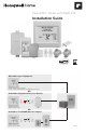
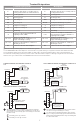
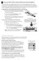
® ™ VisionPRO Series with RedLINK Installation Guide TM Wired Directly to Equipment Dual Powered - C Wire or Battery (C wire or Wire Saver required to use RedLINK accessories) OR RedLINK to Equipment Interface Module TM 2 Wires for Power or Battery Only (no wires) OR RedLINK to TrueZONE Wireless Adapter TM 2 Wires for Power or Battery Only (no wires) M37817
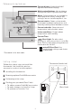
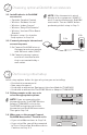
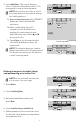
Reference to key features Current display. Underlined label signifies the current display. Mode control buttons. Use to change settings for Fan or System Heat/Cool. Menu. Select options to: set schedules, view equipment status, change IAQ settings, access installer options*, etc. Current status. Shows system mode (heat/cool), outdoor temperature and humidity (with optional outdoor sensor). Current schedule. Shows desired temperature and schedule status. Indoor conditions.
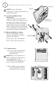
1 Installing the thermostat NOTE: For best RedLINK performance, mount thermostats at least 2 feet apart. Thermostat Button 1.1 Separate wallplate from thermostat. If your thermostat has a button along the top of the wallplate, press button on top and pull to remove the wallplate as shown. Updated models do not have this button. On those models pull evenly along the sides and bottom of the thermostat to separate it from the wallplate. 1.2 Mount wallplate as shown.
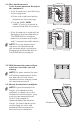
1.4 Wire the thermostat. Is the thermostat wired directly to the equipment? • If the thermostat is wired directly to the equipment: a Refer to the table and wiring diagrams on the next page. CONVENTIONAL C K RC R U1 S1 S1 S1 S1 W O/B Y Y G G U1 W2 U2 AUX -E Y2 Y2 U2 A L/A b Turn on 24VAC NOW. 24VAC (C wire) is required to connect RedLINK accessories.
Terminal Designations Terminal Conventional System Description Heat Pump Description Terminal Common wire from secondary side of cooling transformer. Common wire from secondary side of cooling transformer (if 2 transformers). C Rc* Cooling power. Rc Cooling power. R* Heating power. R Heating power. W Heat Stage 1 O/B W2 Heat Stage 2 AUX-E C Y Changeover valve for heat pumps.
2 Powering optional RedLINK accessories 2.1 Install batteries in RedLINK accessories. • Portable Comfort Control • Wireless Outdoor Sensor* • Wireless Indoor Sensor* • Wireless Entry/Exit Remote* • Wireless Vent and Filter Boost Remote* * Requires setup. See Installer Setup options in Step 3.4. NOTE: If the thermostat is wired directly to the equipment, 24VAC (C wire) is required to connect RedLINK accessories. Turn on 24VAC before performing initial setup in Step 3. 2.
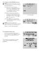
3.3 Connect each RedLINK accessory. NOTE: Accessories must be at least 2 feet away from the thermostat during the linking process. Press Connect on New Accessories. 3.3a While the Press Connect message is displayed (listening mode), press and quickly release the CONNECT button on each new RedLINK accessory. 3.3b After a short delay (up to 15 seconds), check thermostat to confirm the connection of each RedLINK accessory. Touch s or t to review the list. 3.
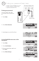
Finding your password (Date Code) • To add or remove RedLINK accessories • To make changes to Installer Setup • To perform an Installer Test 2126 4 1-800-468-1502 Customer.Resideo.com 1 Touch Menu. 2 Select Dealer Information. 4 TH8321R1001 M34161B 2126 TH8321R1001 You can find the date code on the back of the thermostat, or Country of origin: Mexico Pays d’origine : Mexique Manufactured by Resideo Technologies, Inc., RoHS Compliant 1985 Douglas Dr. N.
5 Select Add Device. The screen displays “Press Connect on New Accessories.” The thermostat is now in listening mode. Add Device Connected Devices NOTE: Accessories must be at least 2 feet away from the thermostat during the linking process. 5a Press and quickly release the CONNECT button on each new RedLINK accessory. MCR33981 Press Connect on New Accessories. 5b After a short delay (up to 15 seconds), check thermostat to confirm the connection of each RedLINK accessory.
Using a microSD card for setup, data logs and software upgrades Use a microSD (secure digital) card to save setup time by loading Installer Setup settings, Dealer Information, Holiday Schedules, and Custom Reminders to multiple thermostats. For troubleshooting help, you can save the thermostat Data Logs (Alerts Log and Interaction Log) to a microSD card - then view them on your computer. Also use the microSD card to upgrade the thermostat software.
Specifications and replacement parts Operating Ambient Temperature Thermostat: 32 to 120° F (0 to 48.9° C) Portable Comfort Control: 32 to 120° F (0 to 48.9° C) Wireless Outdoor Sensor: -40 to 140° F (-40 to 60° C) Wireless Indoor Sensor: 0 to 120° F (-17.8 to 48.9° C) -For Optimal Battery Life: 35 to 114° F (1.7 to 45.6° C) Equipment Interface Module: -40 to 165° F (-40 to 73.9° C) Return Air Sensor: 0 to 200° F (-17.8 to 93.3° C) Discharge Air Sensor: 0 to 200° F (-17.8 to 93.
Model Numbering Stages TH8321 TH8320 TH8110 3H/2C HP 2H/2C CONV 3H/2C HP 2H/2C CONV 1H/1C HP 1H/1C CONV P P P 1 1 P P P P P P P 0 1 P P P 0 1 Residential or Commercial Dual Powered - C Wire or Battery Onboard Humidity Sensor Number of IAQ Relays Number of Sensor Inputs Economizer / TOD Output Works with Optional Equipment Interface Module* Works with Optional TrueZONE Wireless Adapter* P P * The relay outputs and inputs on the thermostat do not function when used with an Equipment Interface Mo