
Product Overview
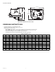
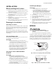
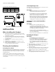
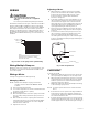

Table Of Contents

7 68-0247—03
WIRING
CAUTION
Personal Electrical Shock Hazard.
Can cause electrical shock or equipment
damage.
Disconnect power before beginning installation.
The ZD has a 24 Vac, 50/60 cycle, 0.32 A motor. The ZD is
wired to terminals M1 and M6 for power closed/spring
return open. See Fig. 6. The ZD is a spring return damper
that requires 24 V to the two motor leads to power the
damper closed. When power is removed from the motor,
the damper springs back to its normally-open position.
When used with Networked Zoning, use closed and com
terminals.
Fig. 6. Power closed spring return open ZD wiring.
Wiring Multiple Dampers
When the same zone controls two or more dampers, wire
the dampers in parallel to terminals M1 and M6 on the
zone control panel.
Wiring a Motor
See Fig. 6 for typical motor wiring hookup.
Changing a Motor
NOTE: All ZD-series dampers (legacy and current
models) can be used with the M847D-ZONE
actuator.
1. Disconnect the motor wiring.
2. Loosen the large Allen set screw located between the
faceplate and the motor coupling.
3. Remove the motor.
4. Ensure damper blades are in the open position with
the set screw pointing toward the open position on
the label.
5. Attach new motor to the coupling; be sure that the
standoff on the motor is positioned in the grommet
on the faceplate and that the set screw is aligned
with the motor shaft hole.
6. Tighten the set screw.
Adjusting a Motor
1. When viewed on end, the lower lever is normally
positioned to the extreme left and the upper lever
positioned to the extreme right. See Fig. 7. This
position provides complete shutoff when the
actuator is energized.
2. To prevent complete closure of the damper, loosen
(do not remove) the wing nut on the bottom of the
unit and move the upper lever to the left until the
desired position is reached. Tighten the wing nut. In
the extreme left position, the damper should stay
open approximately 40° with the power on.
3. The lower lever is normally positioned to the left to
allow the damper to fully open 90° when energized.
See Fig. 7.
4. To restrict the air flow in the open position, loosen
(do not remove) the wing nut and move the lower
lever to the right until the desired position is
reached. Tighten the wing nut. In the extreme right
position, the damper should open approximately 50°
with the power off.
Fig. 7. Air flow adjustment.
CHECKOUT
To check out the ZD:
1. With 24 Vac applied to the motor leads, observe the
motor powering the damper to the closed position.
2. When energized, verify that the actuator connection
coupling rotates in a clockwise direction (as viewed
from the operator base end) and that the damper
shaft turns with the coupling.
3. With power removed, observe the damper returning
to the normally-open position.
NOTE: To remove power, disconnect one wire from the
motor.
4. If the motor does not operate smoothly and without
hesitation throughout the complete opening and
closing stroke, examine the damper and the shaft for
free rotation within the duct.
5. If the full opening and closing is not achieved, check
that the lower adjustment lever is to the extreme left
and the upper lever is to the extreme right. See Fig. 7.
CLOSED M6
M14851A
OPEN M4
COM M1
NOTE:
WHEN INSTALLING ON OLDER MASTERTROL
TM
BOARDS SUCH AS THE MARK V, JUMPER
M2-M5 ON THE PANEL.
UPPER LEVER
WING NUT
LOWER LEVER
M20155A