® Dolphin 7600II Mobile Computer with Windows Mobile® 6.
Disclaimer Honeywell International Inc. (“Honeywell”) reserves the right to make changes in specifications and other information contained in this document without prior notice, and the reader should in all cases consult Honeywell to determine whether any such changes have been made. The information in this publication does not represent a commitment on the part of Honeywell.
Table of Contents Chapter 1 - Agency Approvals Label Locations ....................................................................................................................1-1 LED Safety Statement....................................................................................................1-1 FCC RF Radiation Exposure Statement ........................................................................1-1 Approvals by Country.........................................................................
Overview.............................................................................................................................. 4-1 29-Key Numeric Keyboard............................................................................................. 4-1 38-Key Alpha Keyboard................................................................................................. 4-1 Suspend/Resume ..........................................................................................................
Chapter 7 - Connecting the Terminal Connections Tab ................................................................................................................. 7-1 Infrared Communication ...................................................................................................... 7-2 IrDA Port Location ........................................................................................................ 7-2 Sending Data .......................................................................
Back Panel ....................................................................................................................... 10-3 Powering the HomeBase Device....................................................................................... 10-3 Charging the Main Battery................................................................................................. 10-4 Mounting the Dolphin HomeBase Device..........................................................................
1 Agency Approvals Label Locations Dolphin 7600II terminals meet or exceed the requirements of all applicable standards organizations for safe operation. However, as with any electrical equipment, the best way to ensure safe operation is to operate them according to the agency guidelines that follow. Please read these guidelines carefully before using your Dolphin terminal. Compliance Label Molded-in Text (see page 1-1) Molded-in Text This Class B Digital Device Complies with Canadian ICES-003.
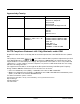
Approvals by Country Country Safety EMC & Radio U.S.A. UL60950-1 (CB Scheme) FCC Part 15, Subpart C, 15.247 FCC Part 15, Subpart B FCC Part 22H FCC Part 24H FCC SAR OET 65 Supplement C Canada cUL60950 ICES-003 (Class B) RSS 132 RSS 133 RSS 210, Issue 7 European Community/CE EN60950-1:2000 EN60825-1:1994 + A11 + A2 IEC60825-1 EN 300328-1/2 EN55022:1998+A1:2000+A2:2003 EN55024:1998+A1:2001+A2:2003 EN301 511 EN301 489-1/-7 EN61000-3-2:2000 EN61000-3-3:1995+A1-2001 R&TTE Compliance Statement—802.
Dolphin RF Terminal—802.11b/g, Bluetooth, and/or GSM This device complies with Part 15 of the FCC Rules. Operation is subject to the following two conditions: (1) this device may not cause harmful interference, and (2) this device must accept any interference received, including interference that may cause undesired operation. This equipment has been tested and found to comply with the limits for a Class B digital device pursuant to Part 15 of the FCC Rules.
In order to avoid the dissemination of those substances in our environment and to diminish the pressure on the natural resources, we encourage you to use the appropriate take-back systems for product disposal. Those systems will reuse or recycle most of the materials of the product you are disposing in a sound way.
2 Getting Started Out of the Box Verify that your carton contains the following items: • Dolphin 7600II mobile computer (the terminal) • Main battery pack (3.7v, Li-ion) • AC power supply • Localized plug adapters • User CD Note: Be sure to keep the original packaging in case you need to return the Dolphin terminal for service; see Product Service and Repair on page 14-1. Step 1. Install the Main Battery ! Use only the Li-ion battery packs provided by Honeywell.
Step 3. Boot the Terminal The terminal begins booting as soon as power is applied and runs by itself. Do NOT press any keys or interrupt the boot process. Only tap the screen when prompted. When the boot process is complete, the Today Screen (see page 2-2) appears and the terminal is ready for use. Today Screen System resets (see Resetting the Terminal on page 3-25) complete on the Today screen.
Icons in the Navigation Bar Indicator Meaning The terminal could not synchronize data with the workstation via ActiveSync New e-mail or text message (SMS) New voicemail New instant message Ringer off Voice call Voice call in progress Calls are forwarded Call on hold Missed call Data call in progress Battery levels (1–4). Tap this icon to open the Power system setting and see the charge percentage (see page 6-12). Critical battery.
Icons in the Navigation Bar Indicator Meaning EDGE connected Roaming Radio is disabled The radio is not connected to a network Radio connected No radio signal The terminal is searching for a signal Radio signal strength Wi-Fi on Wi-Fi data call Pending alarm Bluetooth Selecting Programs Tapping Start opens the drop-down menu, which provides access to the most common system functions and programs. To open a program, tap Start > Programs. Then, tap the program icon on the menu.
Using the Stylus The terminal comes with a stylus inserted into the Stylus Slot (see page 3-10), Use this stylus (or your finger) to select or enter information on the touch screen. The stylus functions as a mouse; generally, a tap is the same as a click. Tap Tap the touch screen once to open menu items and select options. Drag Hold the stylus on the screen and drag across the screen to select text and images. Tap & hold Tap and hold the stylus on an item and a pop-up menu appears.
2-6 Rev (a) 01 5/29/08 Dolphin® 7600II Mobile Computer User’s Guide–Preliminary
3 Terminal Hardware Overview Standard Terminal Configurations WPAN / WLAN / WWAN WPAN / WWAN • • • • • • • • • • • • • Windows Mobile 6.0 Professional Samsung 2440 400 MHz 128MB RAM X 128 MB (non-volatile) Memory 29-key numeric keyboard or 38-key alpha keyboard 2.8” 1/4 VGA TFT color display Li-ion battery: 3.7V / 3240 mAh / 12.0 Wh 5300SR image engine Bluetooth, 802.11b/g, and GSM radio Power cable (included in each box) • • • • • Windows Mobile 6.
Peripherals The following items are sold separately and enhance your terminal’s capabilities. For information about how to purchase these items, contact a Honeywell sales representative. Dolphin HomeBase™ Device The Dolphin HomeBase device is a charging and communication cradle supports USB communication, enabling your terminal to interface with the majority of PC-based enterprise systems. When a terminal is seated in a powered HomeBase device, its main battery pack charges in less than four hours.
Front Panel Features Decode LED Scan LED 1/4 VGA Touch Screen Display (screen protector installed at the factory) Microphone Hardware Application Buttons Keyboard (29-key numeric) Decode and Scan LEDs The Scan LED lights red when you press the Scan trigger in scanning applications. The Decode LED lights green when a scanned bar code is successfully decoded. Both LEDs are user-programmable.
Touch Screen Display The display is a 65,536-color LCD (Liquid Crystal Display) covered by a touch screen lens. The 2.8” 1/4 VGA (Video Graphic Array) is TFT (Thin Film Transistor) color, backlit, and the resolution is 240 x 320; see Display Backlight on page 3-4. Dolphin terminals ship with a screen protector already installed over the touch screen lens to help prevent damage to the touch screen. Do NOT remove this screen protector before initial use.
1. You will need a strong, flat, plastic card (a credit card, for example) to wedge under the existing screen protector. Note: If you have one, you can also use the small plastic squeegees designed for touch panels. 2. Press the Blue + Backlight keys to put the terminal in Suspend Mode (see page 3-26). 3. Carefully apply the flat edge of your plastic card to the upper right corner of the touch panel. Catch the edge of the screen protector and pull it up and away from the touch panel.
4. Wipe the screen with a clean, non-abrasive, lint-free cloth. Note: Use ionized air, if available, to blow additional dirt or particles off the touch panel. Installing Your Screen Protector When installing a new screen protector, use a flat plastic card (such as a credit card) to apply the screen protector smoothly and remove any air bubbles. Note: If you have one, use the small plastic squeegees designed for touch panels. 1.
2. Clean the touch panel thoroughly with a clean, non-abrasive, lint-free cloth. Make sure nothing is attached to the top of the touch panel. 3. Release the left edge of the releasing paper on the screen protector. 4. Align the exposed edge of the screen protector along the left edge of the touch panel. Make sure that it lies flush with edges of the touch panel. Note: To reposition the screen protector, lift up gently and reapply. 5.
6. Pull smoothly and evenly from left to right until the screen protector is applied. Press gently but firmly. Touch Panel 7. Use the card as necessary to smooth out any air pockets or bumps after application. Press gently but firmly. 8. Press the Backlight 9. Verify that the screen accepts input from the stylus as usual. If not, re-apply the screen protector. 10. Press the Blue 3-8 key to wake the terminal and check the touch panel with the stylus.
11. Clean the surface of the screen protector with a clean, non-abrasive, lint-free cloth. 12. Press the Backlight key to wake the terminal. 13. For maximum performance, recalibrate the screen. Tap Start > Settings > System tab > Screen > Align Screen. 14. Follow the instructions on the screen.
Back Panel Features Image Engine Window Accessory Attachment Stylus Slot Rear Speaker Finger Saddle SIM Card Door I/O Connector Accessory Attachment This button can be used with various accessories; see Using the Accessory Attachment on page 3-11. Finger Saddle This is a slightly depressed and angled area of the back panel that is designed to cradle or “saddle” your pointer finger while holding the terminal.
Using the Accessory Attachment The accessory attachment is a standard tab designed to fit universal accessories available for most cell phones. An accessory must be used for body worn operation. Attaching a Belt Clip The accessory attachment on the back panel fits universal swivel clips designed for belts or even pedestal mounts (not available from Honeywell). Simply insert the tab into the slot until you hear a click or follow the instructions that came with the clip or accessory.
Side Panel Features DC Power Jack Headset Jack IrDA Port Side Button Access Door Side Door Note: This graphic shows the left side of the terminal. Access Door This door covers the memory card slot. To increase memory, install a memory card in this slot. This terminal supports microSD™ and microSDHC™ memory cards. For details, see Installing Memory Cards on page 3-14.
Side Door The rubber door on the left side panel provides access to the Headset and DC power jacks. When closed, the side door seals the terminal from moisture and particle intrusion thus preserving the terminal’s environmental rating.
Installing Memory Cards This terminal supports microSD and microSDHC memory cards up to 4GB. To install an SD card, you must open the access door on the side panel (Side Panel Features, page 312). Access door removal requires a Torx 5 (T5). 1. Press the Blue + Backlight keys to put the terminal in Suspend Mode (see page 3-26). 2. Place the terminal on a flat, secure surface with the keyboard face-down. 3. Use a T5 screwdriver to remove the screw on the micro-SD door. 4. Remove the access door. 5.
! Do NOT resume terminal operation while the access door is open! Operating the terminal while the access door is open may cause damage not covered by the warranty. The access door must be properly sealed before resuming terminal operation. Failure to seal the access door may cause damage not covered by the warranty. 6. Replace the access door and tighten the screw. 7. Press the Backlight 8.
Bottom Panel Features I/O Connector Hand Strap Slot Hand Strap Slot There is an adjustable, elastic hand strap available for purchase with the terminal. When installing the hand strap, you loop the elastic strip through this slot. For instructions, see Attaching the Hand Strap on page 3-11. I/O Connector The I/O mechanical connector is designed to work exclusively with peripherals and cables designed for the Dolphin 7600II terminal.
Connecting the USB Cable Connect the USB cable to the I/O connector to facilitate USB communication between the terminal and host workstation. I/O Connector Host Workstation USB Cable *Power Port USB Connector *This is a communication-only cable until you plug the power cable into the power port. Connecting the Power Cable The power port on the back end of the USB connector fits the power cable that comes with each terminal.
ActiveSync Communication To synchronize, ActiveSync 4.5 or higher must be installed and configured for the appropriate communication type on the host workstation and the Dolphin terminal. Dolphin terminals ship with ActiveSync already installed. Therefore, if ActiveSync is already installed on the host workstation, you just need to connect the Dolphin terminal to the host workstation (via Dolphin peripheral) to initiate communication. If ActiveSync 4.
Setting Up the Host Workstation Verify that ActiveSync is configured to use the appropriate communication type by clicking File > Connection Settings. For RS-232 For USB communication, Note: You can have both USB and RS-232 selected in the software without affecting processing. However, your hardware setup should use only RS-232 or USB, not both. Communicating with the Dolphin Terminal After setting up both the workstation and the terminal, ActiveSync connection should be automatic. 1.
The Mobile Device folder opens in Windows Explorer. The terminal is now treated as a mass storage device, and transferring files is as simple as dragging and dropping or copying and pasting as you would for moving files between folders on your hard drive.
Battery Power Dolphin terminals feature intelligent battery technology with two types of battery power: • • The main battery pack on the back panel (see Main Battery Pack on page 3-21) The backup battery located inside the terminal (see Internal Backup Battery on page 3-24) Both batteries work together to prevent data loss when the terminal is used over long periods of time.
• Never throw a used battery in the trash. It contains heavy metals and should be recycled according to local guidelines. • Don’t use a battery in any other manner outside its intended use in Dolphin terminals and peripherals. • Don’t short-circuit a battery or throw it into a fire; it can explode and cause severe personal injury. • Excessive discharge damages a battery. Recharge the battery when your terminal indicates low battery power.
Setting Critical and Low Battery Points Developers can re-reset the default battery points in the RegEdit Power Tool. 1. Tap Start > Power Tools > RegEdit. 2. Drill-down to HKEY_LOCAL_MACHINE > System > CurrentControlSet > Control > Power. 3. Tap the Value Name to change the Value Data. You can reset the Value Data from 0 (no warning) to 99 (would nearly always warn). 4. Tap OK to save changes. Note: These changes will not persist through a cold boot.
Internal Backup Battery Located inside the terminal, the backup battery is a 2.4V nickel metal hydride (NiMH) battery. The internal backup battery prevents the terminal from being reset when you remove the main battery pack. This battery retains RAM data and allows the real-time clock to remain operational for up to 30 minutes.
Resetting the Terminal There are two ways to reset the Dolphin terminal: a soft reset and a hard reset. Soft Reset (Warm Boot) A soft reset re-boots the terminal without losing RAM data. You would perform a soft reset 1) when the terminal fails to respond, 2) after installing software applications that require a reboot, or 3) after making changes to certain system settings. 1. Press and hold Red + ESC for approximately 5 seconds.
Suspend Mode Suspend mode suspends terminal operation. The terminal appears to be “off” when in suspend mode. The terminal is programmed to go into suspend mode automatically when inactive for a specified period of time. You can set this time period in the Power setting. To Put the Terminal in Suspend Mode Press the Blue + Backlight keys. Note: You should always put the terminal in suspend mode when you change the battery pack; see Changing the Main Battery Pack on page 3-21.
4 Using the Keyboards Overview There are two keyboard options: a 29-key keyboard and the 38-key keyboard. 29-Key Numeric Keyboard 38-Key Alpha Keyboard P2 P1 P3 P4 SCAN SEND END ESC PG SFT PG F1 1 F4 4 GHI F7 7 PQRS TAB F3 F2 2 ABC 3 DEF F6 F5 5 JKL 6 MNO F9 F8 8 TUV 9 WXYZ F10 BKSP 0 SP START . The buttons are recessed under the overlay for maximum durability and the panel is backlit for maximum viewability in various lighting conditions.
Function Keys Function keys appear on both keyboards and perform specific functions. Name Key Function Backlight Toggles the keyboard backlight on and off. Backspace Backspace moves the cursor back one space. If you are typing text, a character is deleted each time you press the backspace key. Escape Cancels an action. Enter Performs the same function as the Enter key on a PC or workstation. Scan • Activates the image engine to scan a bar code or take an image.
Alpha/Numeric Indicator The Navigation bar features an icon that indicates the alpha/numeric status of the keyboard. This icon changes when the keyboard status changes. Icon Keyboard Status The keyboard is in lowercase alpha mode. The keyboard is in shifted (uppercase) alpha mode. The keyboard is in numeric mode.
29-Key Numeric Keyboard Hardware Application Buttons P2 P3 P1 Escape P4 SCAN SEND END ESC PG SFT PG Navigation Keys Scan Enter Shift TAB Tab F1 1 2 ABC F4 5 JKL F7 6 MNO 8 TUV 9 WXYZ F10 BKSP 0 Alpha Indicators F9 F8 7 PQRS 3 DEF F6 F5 4 GHI Backspace F3 F2 START Space SP . Backlight Modifier Keys Navigation Keys Located in the center of each keyboard for easy access with either hand, the navigation keys enable you to move the cursor through application screens.
Hardware Application Buttons These four buttons are programmed to launch software applications when the Today Screen (see page 2-2) is on the screen. Hardware Application Buttons P2 P3 P1 SCAN P4 SEND END To customize these settings, tap Start > Settings > Personal tab > Buttons Buttons Column Matching Hardware Button Buttons 1–4 Buttons P1—P4 on the 29-key keyboard. Left Left side button; see Side Button on page 3-12. Right Right side button; see Side Button on page 3-12. .
Toggling Between Alpha and Numeric Modes The 29-key keyboard defaults to numeric mode, which means that the keyboard boots up to numeric mode after each hard reset. Numeric mode is when you type numbers with the number keys. Alpha mode is when you type letters or characters with the number keys. The keyboard switches between alpha and numeric modes easily.
29-Key Blue Key Combinations (Alpha Mode) Tap the Blue modifier key to switch to alpha mode for the next key pressed. Double-tap the Blue modifier key to switch to alpha mode permanently.
Key Character 9 ( 0 ) 29-Key Red Key Combinations Special Characters Key Combination Character Red + Left Arrow - Red + Right Arrow + Red + BKSP * Red + SP # Red + . , Red + P1 / Red + P2 = Red + P3 ; Red + P4 \ Functions 4-8 Key Combination Function Red + ESC (hold) Soft reset (warm boot) Red + TAB (hold) Hard reset (cold boot) Red + Up Arrow Page up Red + Down Arrow Page down Red + 1 F1 Red + 2 F2 Red + 3 F3 Red + 4 F4 Red + 5 F5 Red + 6 F6 Red + 7 F7 Re
Key Combination Function Red + 9 F9 Red + 0 F10 Dolphin® 7600II Mobile Computer User’s Guide–Preliminary Rev (a) 01 5/29/08 4-9
38-Key Alpha Keyboard Scan Navigation Keys Tab Backspace Enter Escape Space Shift Backlight NUM Lock Key Modifier Keys Toggling Between Alpha and Numeric Modes The 38-key keyboard defaults to lowercase alpha mode, which means that the keyboard boots up to lowercase alpha mode after each hard reset. Numeric mode is when you type numbers with the number keys. Alpha mode is when you type letters or characters with the number keys. The keyboard switches between alpha and numeric modes easily.
38-Key Red Key Combinations Key Combination Function Red + ESC (hold) Soft reset (warm boot) Red + TAB (hold) Hard reset (cold boot) Red + Down Arrow P1 Red + Up Arrow P2 Red + Left Arrow P3 Red + Right Arrow P4 Red + Left Side Button P5 Red + Right Side Button P6 Red + A F1 Red + F F2 Red + K F3 Red + P F4 Red + U F5 Red + E F6 Red + J F7 Red + O F8 Red + T F9 Red + Z F10 38-Key NUM Lock Mode • To switch to numeric mode for the next key pressed, tap the NUM key once.
Numbers Key Character B 1 C 2 D 3 G 4 H 5 I 6 L 7 M 8 N 9 R 0 Key Character J \ Q .
5 Using the Image Engine Overview The Dolphin terminal houses a compact image engine using Adaptus™ Imaging Technology that instantly reads all popular 1D and 2D bar codes and supports omni-directional aiming and decoding. The image engine can also capture digital images. *Pull the plastic tab to remove the plastic film cover over the image engine window before activating the image engine. Available Engines 5300 Standard Range (5300SR) 8.3 mil Linear *Working Range: 10 mil PDF417 (.020cm) (.
Supported Bar Code Symbologies Symbology Type Symbology Name 1D Symbologies Codabar Code 3 of 9 Code 11 Code 32 Pharmaceutical (PARAF) Code 93 Code 128 EAN with Add-On EAN with Extended Coupon Code EAN-8 EAN-13 GS1-128 GS1 Databar Interleaved 2 or 5 2D Symbologies Aztec Codablock Code 16K Code 49 Composite Data Matrix GS1 Databar MaxiCode Micro PDF OCR PDF417 QR Code Composite Codes Aztec Mesa Codablock F EAN·UCC GS1 Databar-14 OCR OCR US Money Font MICR (E 13 B) and SEMI Font OCR-A OCR-B Postal C
Activating the Engine When a scanning application is open, press the SCAN key to activate the image engine. You can also press one of the side buttons (see page 3-12), which are programmed to activate the image engine in a scanning application by default. Using Demos Demos are software utilities loaded on all Dolphin terminals that demonstrate the advanced features of the terminal. There are two Demos feature the image engine: Image Demo and Scan Demo.
Sample Bar Codes You can use the following bar codes to verify decoding: Sample 128 Sample PDF417 Code 128 PDF417 Test Message Omni-Directional Scanning Positions The high-vis aiming pattern frames the bar code to provide you with the best scanning performance. Note: To achieve the best read, the aiming beam should be centered horizontally across the bar code. The aiming pattern is smaller when the terminal is held closer to the code and larger when the terminal is held farther from the code.
Capturing Images The image-capture process is an intuitive, split-second operation for experienced users. By following basic guidelines, however, new users can easily develop their own technique and, with practice, quickly learn to adapt to different application environments. Image Preview When the imaging process is initiated, the touch screen displays a preview of the object.
5-6 Rev (a) 01 5/29/08 Dolphin® 7600II Mobile Computer User’s Guide–Preliminary
6 System Settings Overview Customized settings are available on the Start menu. Tap Start > Settings and settings screen opens displaying the Personal tab. Settings consists of three tabs: Personal, System, and Connections. Personal Tab System Tab Connections Tab Tab Description See Page Personal Customizes buttons, set SIP options, and adjust headset settings. 6-2 System Adjusts system settings. 6-7 Connections Establishes network connections settings.
Personal Tab To access the Personal tab, go to Start > Settings. The screen opens displaying the Personal tab. Icon Description For more information… Buttons Program the side buttons to perform specific tasks. See Buttons on page 6-3. Input Customizes the SIP. See Input on page 6-4. Lock Password protect the terminal to limit access to the terminal. Menus Customizes what appears on the Start menu. Owner Information Enter your contact information.
Buttons Buttons programs both keyboard buttons and the side buttons to launch applications or execute commands. The default button assignments that appear on the Buttons window are inactive until you enable the HotKeys Power Tool. To Enable HotKeys 1. Tap Start > Power Tools and tap the HotKeys icon once assignments in the Buttons setting are active. 2. Verify the assignment by tapping the button on the keyboard. .
Additional Functions The Assign a program list also contains the following commands: Command Description Opens the soft input panel. Nothing happens when the button is pressed. This is the default setting for the LSide and RSide buttons and means that pressing either button activates the image engine. Performs the same function as tapping OK on the screen. Scrolls down in the open application. Scrolls left in the open application.
Menus You can add existing programs you use often, such as File Explorer, to the Start menu for faster access. You are not installing the program, just allowing access to it from the Start menu. To add programs to the Start menu, you can use • The Menus setting on the Personal tab (see page 6-5), • File Explorer (see page 6-5), or • ActiveSync (see page 6-6). Note: The Start menu can hold only seven applications at a time. Using System Settings 1. Tap Start > Settings > Personal tab > Menus . 2.
2. Tap and hold on the program, then tap Copy on the pop-up menu. 3. Navigate to the Windows folder and open the Start Menu (My Device > Windows > Start Menu), tap and hold a blank area of the window, and tap Paste Shortcut on the pop-up menu. 4. Tap the Start menu to verify that the program now appears on it.
System Tab The System tab enables you to verify and sometimes alter system parameters. To access the System tab, go to Start > Settings > System tab. Tap the appropriate icon to open that system setting. For details, • See About on page 6-7. • See Backlight on page 6-8. • See Certificates on page 6-8. • See ClearType Tuner on page 6-9. • See Clock & Alarms on page 6-9. • See Encryption on page 6-9. • See Error Reporting on page 6-9. • See External GPS on page 6-10. • See Memory on page 6-10.
Backlight The Backlight system setting enables you to customize backlight functionality for the display. The backlight for the color display is user-defined. Tap Start > Settings > System tab > Backlight. There are two tabs: The Battery tab determines display backlight settings when the terminal is running on battery power. The External tab determines display backlight settings when the terminal is running on external power. The options on each tab are the same.
ClearType Tuner This system setting enables you to adjust the level ClearType font rendering by moving a slider. The sample text displays the setting results immediately. Of course, you must first enable ClearType font rendering to change the appearance of fonts on the screen; see ClearType Tab on page 6-14. Clock & Alarms This setting sets the system clock, which means that all scheduled items run according to this setting.
External GPS External GPS is a Microsoft tool that enables you to connect an external GPS device to the terminal. You need the installation parameters from the GPS manufacturer to configure the connection. You can connect an external GPS device to the terminal via the I/O connector or the Bluetooth radio. Which method you choose determines which COM port you choose. Memory The Memory system setting displays capacity and usage statistics for both RAM (volatile) and IPSM/ Storage Card (non-volatile) memory.
This tab displays the current capacity and usage statistics of the selected memory type; IPSM or Storage Card. Select the memory type from the drop-down list. IPSM is selected by default. Storage Card Tab Total storage card memory=The total MB of memory capacity of IPSM or Storage Card. In use=The MB currently being used. Free=The MB that is still available for use. IPSM—Short for Internal Persistent Storage Manager, this is the on-board Flash memory that is non-volatile.
Power Power system settings contains three tabs: Battery and Advanced. Battery Tab Displays the remaining charge of batteries. For more information about the terminal’s batteries, see Battery Power on page 3-10. Advanced Tab Determines power time-outs. For On battery power, select from the drop-down list, the number of minutes of inactivity you want to pass before the terminal powers off when running on battery power.
Remove Programs Remove Programs enables you to remove programs installed on the terminal. Use this setting to troubleshoot when you receive messages that the terminal is out of memory. The programs removed are removed from RAM memory. Any program (usually CAB or DLL files) stored in the Autoinstall folder (My Device > IPSM > Autoinstall) will re-install after the next hard reset. For information about the Autoinstall process, see Let Autoinstall Run on page 2-7.
Screen The Screen system setting contains three tabs: Alignment, Clear Type, and Text Size. Alignment Tab Orientation–The default orientation for the screen is Portrait. Select one of the Landscape options to change the screen orientation. Align Screen–You need to re-align the screen if tapping buttons or icons with the stylus no longer seems to work appropriately. Tapping Align Screen brings up the align screen window where you are guided to tap a target several times.
WAN Info When the GSM radio is active, WAN Info displays useful statistics for the radio. To verify whether or not the GSM radio is enabled, check the Dolphin Wireless Manager (see page 7-6).
6 - 16 Rev (a) 01 5/29/08 Dolphin® 7600II Mobile Computer User’s Guide–Preliminary
7 Connecting the Terminal Connections Tab The Connections system setting provides access to the terminal’s various communication options. Icon Description See Page Beam Enables and disables infrared receiving. 7-3 Configures the Bluetooth connection. This icon appears only if a Bluetooth radio and driver is installed on the terminal. 9-1 Bluetooth Connections Opens the connections manager. 7-4 Dolphin Wireless Manager Manages the wireless radios installed in the terminal.
Infrared Communication Using the IrDA port, you can send and receive data between the terminal and other devices equipped with infrared. This can include, but is not limited to, Windows Mobile information such as Contacts and Tasks, as well as software upgrades. The maximum data transfer speed is 115 Kbps. IrDA Port Location IrDA Port To send or receive, the IrDA ports of both devices - whether it’s two terminals, or a terminal and a host device - must be aligned with each other and within a close range.
5. When the IrDA port finds the IrDA port of the other device, it immediately starts sending the selected file. The selected device reads “Sending.” 6. When the file transfer is complete, the selected device reads “Done.” Receiving Data The Beam Setting must be set to receive for the terminal to receive data from other infrared devices. 1. Verify that beam settings are set to receive. Tap Start > Settings > Connections tab > Beam. The Beam Settings window should appear as follows: 2.
Connections Manager The connections manager sets up various network connections to Internet Service Providers (ISPs) via external modem. To open the connections manager, tap Start > Settings > Connections tab > Connections icon . Server-Assigned IP Addresses All server-assigned IP addresses use Dynamic Host Configuration Protocol (DHCP). Zero-Config Wi-Fi The zero-config Wi-Fi feature of Windows Mobile is disabled on Dolphin 7600II terminals.
Proxy Server Connections If you are connected to your ISP or private network during synchronization, the terminal should download the proper proxy settings during synchronization with the PC. If these settings are not on your PC or need to be changed, ask your ISP or network administrator for the proxy sever name, server type, port, type of Socks protocol used, and your user name and password.
Dolphin Wireless Manager The Dolphin Wireless Manager provides a centralized interface that enables and disables all the on-board radios. Each radio has its own configuration program and the Dolphin Wireless Manager also provides shortcuts to the configuration utilities for each radio. There are three radio options: 802.11b/g, GSM/GPRS, and Bluetooth. 1. 802.11b/g If the 802.11b/g radio is installed on the terminal and there is no GSM radio installed, the 802.
Enabling the Radios 1. Tap Start > Settings > Connections tab > Dolphin Wireless Manager . 2. Tap anywhere inside the rectangle or the OFF button inside the rectangle. The radio begins activating. 3. When the radio is activated (i.e., transmitting a signal), the OFF button changes to ON. Note: If applicable, information about the radio appears in the rectangle.
Installing Additional Software Dolphin terminals ship with the operating system, radio drivers, and custom Honeywell software already installed. These default programs install when your terminal first boots up. You can install additional software programs to the terminal provided that the following parameters are met: • • • The software program was created for the Windows Mobile platform. The terminal has enough memory to store and run the program. The program has an EXE, CAB, or DLL extension.
If the File is Not an Installer Some programs cannot be installed on workstations because they are designed exclusively for Windows Mobile-based devices. In these cases, the appropriate files must be stored on the host workstation and transferred to the terminal via ActiveSync Explore. Note: You know that the program is not an installer because an error message stating that the program is valid but designed for a different type of computer appears when you try to install the program on the workstation. 1.
COM Port Assignment Table The terminal ships with the com ports assigned as follows: COM Port Assignment Description COM1 GSM Siemens GSM radio (not accessible) COM2 Serial port RS-232 Connector on the bottom panel COM3 Raw IR Raw Infrared (not accessible) COM4 IrDA Serial Infrared (SIR) up to 115 Kbps COM5 USB Serial Virtual USB Serial port for ActiveSync COM6 BT Stack Bluetooth Stack (not accessible) COM7 BT DUN Bluetooth_DUN (not accessible) COM8 BT Serial Bluetooth serial inter
Network Cards The Network Cards setting displays the network cards installed in the terminal. 1. Tap Start > Settings > Connections > Network Cards. 2. Tap on an adapter in the list to review its settings. (Server-assigned IP addresses use DHCP.) 3. If you make a change on one of these tabs, tap OK to confirm the changes. 4. You must perform a soft reset to update the registry entries; see Soft Reset (Warm Boot) on page 315.
USB to PC The USB to PC applet enables you to switch between RNDIS (Remote Network Driver Interface Specification) USB and Serial USB communication. Dolphin 7600II terminals default to Serial USB. Honeywell recommends using Serial USB. To change this setting, tap Start > Settings > Connections tab > USB to PC is not selected, which indicates Serial USB. . The enable option To switch to RNDIS USB, select Enable advanced network functionality and tap OK to save. (Wait as the terminal makes the change.
8 Working with GSM Overview The Dolphin 7600II can be configured with an integrated Siemens® GSM/GPRS EDGE quad-band radio module for WWAN communications. GSM Short for Global System for Mobile communications, GSM is an open, non-proprietary wireless WAN system that is constantly evolving and growing. GPRS Short for General Packet Radio Service, GPRS is a non-voice value added service that allows packet-switched data to be instantly sent and received across mobile telephone networks.
SIM Card Installation Short for Subscriber Information Module, a SIM card stores the subscriber's personal information, GSM/ GPRS radio settings, security keys, contacts, etc. SIM cards can be installed in multiple devices, which enables you to switch devices without losing personal and setup information. SIM Card Requirements Before installing the SIM card: • The SIM card must be activated by the service provider. • The terminal must be powered down (suspend mode).
8. Fasten the SIM card door. 9. Insert the battery pack and tap the SCAN key to wake the terminal from Suspend mode. 10. When the operating system recognizes the new SIM card, a notification message pops up. Enabling the GSM Radio Be default, the GSM radio should be enabled after each hard reset. Verify the status of the radio in the Dolphin Wireless Manager. 1. Tap Start > Settings > Connections tab > Dolphin Wireless Manager . 2.
Data Communication You set up data communication via the connections manager. The carrier on the SIM card is the ISP. System Requirements • The GSM radio must be enabled; see Enabling the GSM Radio on page 8-3. • You must have an active SIM card installed; see SIM Card Installation on page 8-2. • The Phone must not be in use. The but the phone is not in use.
4. Enter the APN and tap Next. 5. Enter the username and password from the account and tap Finish. 6. On the Connections window, tap Manage existing connections. The connection you just created should appear in the list on the modem tab.
7. Tap and hold on the connection and select Connect on the popup menu. 8. The network icon in the Navigation bar indicates the GSM radio is attempting to connect 9. When the connection is complete, the network icon changes to: . . 10. You can now send data over GSM. Ending the Data Connection You need to end the data connection to use the phone. By default, the data connection will disconnect after a certain amount of time passes without use. This period of time is determined by ISP.
Voice Communication You can use the Dolphin terminal as a phone via the GSM radio. Audio Modes There are two audio modes: Speakerphone and Headset. Speakerphone Use the microphone on the front panel and the speaker on the back panel to operate the GSM phone in Speakerphone mode. Speakerphone is the default audio mode. Headset Headset mode is when you use a headset with earplug for audio input and the microphone for audio output.
Accessing the Dialer Window When the GSM radio is active, tap Start > Settings > Connections tab > Dolphin Wireless Manager, then tap Menu > Phone Settings. The Phone dialer opens. Displays the network carrier from the SIM card. Displays the most recent calls. Dialing Once the dialer window is open you can dial out two ways: • Tap the buttons on the dialer window. • Use the physical keyboard (when it’s in numeric mode).
Setup Options Tap Menu > Options. You can also tap Start > Settings > Personal tab > Phone when the GSM radio is enabled. The Phone Settings tab windows appear. Phone Tab Services Tab Establish or change the terminal’s PIN on the Phone tab. This is the PIN that other Bluetooth devices will need to enter to pair with the terminal. For each service, the phone will read You can set networks on the Network settings from the network on the SIM tab. and display the available options from the carrier.
8 - 10 Rev (a) 01 5/29/08 Dolphin® 7600II Mobile Computer User’s Guide–Preliminary
9 Working with the Bluetooth Radio Enabling the Bluetooth Radio You enable the Bluetooth radio in the Dolphin Wireless Manager (see page 7-6). 1. Tap Start > Settings > Connections tab > Dolphin Wireless Manager . 2. Tap anywhere inside the Bluetooth rectangle and Bluetooth begins activating. 3. When the radio is activated (i.e., transmitting a signal), the OFF button changes to ON. Now, the Bluetooth radio is transmitting a signal.
Connecting to Other Bluetooth Devices You need to perform a device discovery and then select a discovered device and connect to it. Pairing happens as part of the connection process. 1. In the Dolphin Wireless Manager, tap Menu > Bluetooth Settings. OR Tap Start > Settings > Connections tab > Bluetooth . 2. Tap Add new device. The terminal begins searching for discoverable Bluetooth devices. 3. Select a device in the list and tap Next.
4. You are prompted to enter a passcode. If the device has a specific passcode, enter it in the Passcode field and tap Next. If the device does not have a specific passcode, enter one in the Passcode field and tap Next. The Bluetooth radio tries to connect with the device. 5. If you created a passcode, you will be prompted by the other device to enter the same passcode. Enter the created passcode to establish a paired connection.
8. The device appears in the list on the main window. 9. After the passcodes have been accepted on both sides, you have a trusted (“paired”) connection. Pairing and Trusted Devices The terminal does support pairing. Pairing happens during general connection setup. Paired devices are "trusted" devices. This means that there is unrestricted access to all services (including services that require authorization and authentication). A connection can exclude pairing.
Types of Devices and Services When you tap Add new device on the Devices tab, the Bluetooth radio scans for discoverable Bluetooth devices in range, which are Bluetooth devices that have been made discoverable. Device Types The types of devices in the vicinity of the radio appear in the list of discovered devices. Supported Services Only the services that are mutually supported on both devices appear on the Partnership Settings window.
Connecting to Bluetooth Printers 1. Make sure the Bluetooth printer is in range and set to be discoverable by other Bluetooth devices. 2. Look up the Bluetooth printer’s broadcasted ID. 3. Perform a device discovery (Tap Settings > Connections > Bluetooth > Add new device.) 4. Look for the Bluetooth printer’s broadcasted ID in the list of discovered devices. 5. Click on the Bluetooth printer’s ID and wait for the prompt to enter a Passcode. 6. Enter the Passcode and tap Next.
Transferring Files 1. Tap Start > Programs > File Explorer. 2. Navigate to the file you want to transfer. 3. Tap and hold on the file and select Beam File on the popup menu. 4. The Bluetooth radio begins searching for devices. When a Bluetooth device is first found, it appears as an Unknown device; the icon indicates that the device is a Bluetooth device. As data is retrieved, the device IDs appear in the list. 5. Tap the device to begin sending the selected file. 6.
9-8 Rev (a) 01 5/29/08 Dolphin® 7600II Mobile Computer User’s Guide–Preliminary
Making the Terminal Discoverable By default, the Dolphin terminal is not discoverable, which means that the terminal will not be found by other Bluetooth devices. To make the terminal discoverable, tap the Mode tab. Select Make this device visible to other devices and tap OK.
9 - 10 Rev (a) 01 5/29/08 Dolphin® 7600II Mobile Computer User’s Guide–Preliminary
10 Dolphin HomeBase Device Overview The Dolphin HomeBase device is a charging and communication cradle that supports full-speed USB 1.1 communication with a workstation. You can also purchase a serial RS-232 HomeBase device. Battery Charging The HomeBase device completes a full charge of the main battery pack in less than four hours. In addition to charging, the HomeBase device powers the intelligent battery charging system in the terminal that protects the battery from being damaged by overcharging.
Front Panel Terminal Well Dock LED Terminal Well Place the terminal in this well to communicate with a host device, power the terminal, and charge its battery. Dock LED Turns solid green when the terminal is properly seated in a powered HomeBase device. When this light is on, the terminal is connected to the HomeBase device. Rubber Feet The bottom panel has four rubber feet–one at each corner–to stabilize the unit on a flat surface.
Back Panel DC Power Jack Pivot Connector USB Port Pivot Connector This pivoting connector swivels 90 degrees. The default position is horizontal, with the connectors facing straight out the back panel. The pivot connector stops in both the horizontal and vertical positions, with the connectors facing out the bottom panel. DC Power Jack Connect the power cable to this power jack; see Powering the HomeBase Device on page 103. USB Port This USB port is full-speed (v1.1).
3. Plug the connector into the DC power jack on the back panel. The HomeBase is now powered. When a terminal is properly seated in the terminal well, the HomeBase powers the terminal, charges the terminal’s main battery pack, and launches ActiveSync (see ActiveSync Communication on page 3-18). Honeywell recommends that you leave the HomeBase connected to its power source at all times, so that it is always ready to use.
Mounting the Dolphin HomeBase Device If you want to mount the HomeBase to a vertical surface, be sure to provide enough workspace with good lighting for the user to view and operate the Dolphin terminal while it is seated in the HomeBase. Back Panel Dimensions .15 in. (3.85 mm.) .32 in. 8.06mm Diameter, 2 places 1.44 in. (36.7 mm.) .53 in. 13.65mm, 2 places 3.99 in. (101.42 mm.) 1.85 in. (46.87 mm.) 4.35 in. (110.47 mm.) Mounting Guidelines 1.
Bottom Panel Dimensions .55 in. (14.07 mm.) .67 in. (16.97 mm.) 3.73 in. (94.88 mm.) Note: The pivot connector should be facing straight out the bottom panel (as shown) when mounting the HomeBase to a vertical surface.
Dolphin QuadCharger Device Overview The Dolphin QuadCharger device is a four-slot charging station that charges up to four Li-ion battery packs in four hours. For more details about charging, see Battery Charging on page 11-3. Use only the peripherals, power cables, and power adapters from Honeywell. Use of peripherals, ! cables, or power adapters not sold/manufactured by Honeywell may result in damage not covered by the warranty. ! Use only the Li-ion battery packs provided by Honeywell.
Back Panel Power Supply Connector Power Switch Power Supply Connector Use this connector to attach the power supply to the QuadCharger device. The universal power supply accepts input voltages between 90-265 volts. Power Switch Toggle the power switch to turn the QuadCharger device on and off. Supplying Power to the QuadCharger Device Use the power adapter cable that comes with the QuadCharger device so that the input voltage is adjusted appropriately. 1.
Battery Charging Inserting and Removing Battery Packs To insert a battery pack, place the end of the battery without the locking tab into the bottom of the charging pocket and snap the battery into place with a hinging motion. To remove a battery pack, push the locking tab down and pull the battery away from the charging slot with a hinging motion. Charging Process The QuadCharger device charges Li-ion battery packs in four hours. Each charging slot works independently of the other three.
Mounting the QuadCharger Device The QuadCharger device should be mounted on a dry, stable surface such as a desktop or workbench, or a flat, vertical surface such as a wall. Mounting Location When choosing a location for the QuadCharger device: • Keep in mind that the mounting location must allow users easy access to power switch and power connector. • Do NOT place the QuadCharger device in an enclosed space because restricted air flow can cause the temperature to elevate, which can effect charging.
2. Drill two holes into the wall, using the slots of the DIN Rail to locate. To ensure stability, holes should be located at least 4 inches (101.6mm) apart. 3. Insert a screw into each hole.
Troubleshooting If you encounter problems with the QuadCharger device, refer to chart below for possible solutions. If problems persist, please contact Technical Assistance (see page 14-2). Problem Issue The Status LED does not come on when I insert a battery pack into a slot. Check the power connections on the QuadCharger device; make sure the POWER switch is ON and the battery pack is properly seated. The Status LED lights red during charging.
Dolphin Mobile Mount Overview The Dolphin Mobile Mount provides easy and secure access to the Dolphin terminal in mobile environments. ! Use only the peripherals, power cables, and power adapters from Honeywell. Use of peripherals, cables, or power adapters not sold/manufactured by Honeywell may result in damage not covered by the warranty. Out of the Box The Dolphin Mobile Mount ships with • The plastic mount, which holds one terminal.
2. The latch at the top should grip the back of the image engine window slot.
Mounting The Dolphin Mobile Mount ships with a standard RAM mount (101B). You attach one ball joint that you attach to the back panel of the mount (with the fasteners provided).
Then, you attach the rest of the RAM mount. Then, fasten the RAM mount to a stable surface.
Technical Specifications Terminal Technical Specifications Basic Features Operating System: BT & BT/ WLAN Configurations: Windows CE 5.0 GSM Configurations: Windows Mobile 6.0 Development Environment: Honeywell SDK for Windows Mobile 6.
1D Symbologies: Codabar, Code 3 of 9, Code 11, Code 32, Pharmaceutical (PARAF), Code 93, Code 128, EAN with Add-On, EAN with Extended Coupon Code, EAN-8, EAN-13, GS1-128, GS1 Databar, Interleaved 2 or 5, ISBT 128, Matrix 2 of 5, MSI, Plessey, PosiCode, Straight 2 of 5 IATA, Straight 2 of 5 Industrial, Telepen, Trioptic Code, UPC, UPC-A, and UPC-E 2D Symbologies: Aztec, Codablock, Code 16K, Code 49, Composite, Data Matrix, GS1 Databar, MaxiCode, Micro PDF, OCR, PDF417, and QR Code Composite Codes: Aztec
Dimensions: BT & BT/WLAN Configurations: 7.0 in. long X 2.7 in. wide X 1.7 in. deep (17.8 cm. long X 6.9 cm. wide X 4.2 cm. deep) GSM Configurations: 7.1 in. long X 2.7 in. wide X 1.9 in. deep (18 cm. long X 6.9 cm. wide X 4.7 cm. deep) Weight: BT & BT/WLAN Configurations: Approximately 11.7 oz./332g GSM configurations: Approximately 14.3 oz.
Dolphin HomeBase Device Structural Dimensions 4 in. high X 4.4 in. wide X 3.7 in. deep (10.2 cm. X 11.2 cm. X 9.4 cm.) Weight 11.2 oz.
Dolphin HomeBase Device Fire Retardant: UL 94-VO Dolphin® 7600II Mobile Computer User’s Guide–Preliminary Rev (a) 01 5/29/08 13 - 5
Dolphin QuadCharger Device Structural Dimensions 11 in. long X 4.8 in. wide X 1.5 in. high (27.9 cm. long X 12.2 cm. wide X 3.8 cm. high) Weight 15.1 oz. (428g) Material Case: Polycarbonate ABS blend Color: Gray Mounting Use DIN rail slide to mount to a desktop or wall; see DIN Rail Dimensions on page 11-4.
Customer Support Product Service and Repair Honeywell provides service for all its products through service centers throughout the world. To obtain warranty or non-warranty service, contact the appropriate location below to obtain a Return Material Authorization number (RMA #) before returning the product. North America Telephone: (800) 782-4263 Fax: (803) 835-8012 E-mail: naservice@handheld.com Latin America Telephone: (803) 835-8000 Telephone: (800) 782-4263 Fax: (239) 263-9689 E-mail: laservice@handheld.
Technical Assistance If you need assistance installing or troubleshooting, please call your Distributor or the nearest technical support office: North America/Canada Telephone: (800) 782-4263 Fax number: (315) 554-6705 E-mail: natechsupport@handheld.com Latin America Telephone: (803) 835-8000 Telephone: (800) 782-4263 E-mail: latechsupport@handheld.com Brazil Telephone: +55 (21) 3535-9100 Fax: +55 (21) 3535-9105 E-mail: brsuporte@handheld.
Limited Warranty Honeywell International Inc. ("Honeywell") warrants its products to be free from defects in materials and workmanship and to conform to Honeywell’s published specifications applicable to the products purchased at the time of shipment.
How to Extend Your Warranty Honeywell offers a variety of service plans on our hardware products. These agreements offer continued coverage for your equipment after the initial warranty expires. For more information, contact your Sales Representative, Customer Account Representative, or Product Service Marketing Manager from Honeywell, or your Authorized Reseller.
Honeywell 700 Visions Drive P.O.