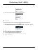
Preliminary Draft 1/19/11 5. When the IrDA port finds the aligned IrDA port, it immediately starts sending the selected file. The selected device reads “Sending.” 6. When the file transfer is complete, the selected device reads “Done.” Receiving Data The Beam Setting must be set to receive all incoming beams from other infrared devices. 1. Verify that beam settings are set to receive. Tap Beam Settings window should appear as follows: > Settings > Connections > Beam. The 2. Align the IrDA ports. 3.
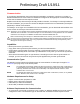
Preliminary Draft 1/19/11 Connections Manager Microsoft’s Connections Manager sets up multiple network connections to Internet Service Providers (ISPs) via external modem. Do NOT enter connection parameters in the Connections Manager if: • You are using one of the on-board wireless radios to connect to a network. The Dolphin terminal uses the settings from each radio’s configuration utility to connect. • You are using Wireless Zero Config. By default, WZC is disabled on Dolphin terminals.
Preliminary Draft 1/19/11 • Proxy server connection Note: If you are connected to your ISP or private network during synchronization, the terminal should download the proper proxy settings during synchronization with the PC. If these settings are not on your PC or need to be changed, ask your ISP or network administrator for the proxy sever name, server type, port, type of Socks protocol used, and your user name and password.
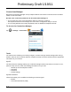
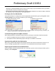
Preliminary Draft 1/19/11 Dolphin Wireless Manager The Dolphin Wireless Manager provides a centralized interface that enables and disables all the onboard radios. Each radio has its own configuration program. The Dolphin Wireless Manager also provides shortcuts to the configuration utilities for each radio. Tap on the Home screen to access the Dolphin Wireless Manager. OR 1. Tap once on the Title bar to access the Horzontal Scroll bar. 2. Tap 3. Select, “Dolphin Wireless Manager”. .
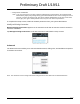
Preliminary Draft 1/19/11 3. The radio begins activating. 4. When the radio is activated (i.e., transmitting a signal), the OFF button changes to ON. Note: If applicable, information about the radio appears in the rectangle. Accessing Radio Configuration Utilities Each of the four radios has its own configuration utilities that you can access through the Menu. There are four radio configuration utilities: For 802.11a/b/g/n: Tap WLAN Settings and the Honeywell WLAN Security Supplicant opens.
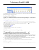
Preliminary Draft 1/19/11 Communication To synchronize data between the terminal and the workstation, ActiveSync (version 4.5 or higher) or Windows Mobile Device Center must be installed and configured for the appropriate communication type on the host workstation and the Dolphin terminal. Dolphin terminals ship with ActiveSync already installed.
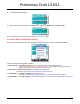
Preliminary Draft 1/19/11 ActiveSync or Windows Mobile Device Center must be setup on your workstation before you initiate synchronization from the terminal for the first time. • Windows 98 Second Edition, Windows Me, Windows 2000, Windows NT (4.0 SP6 or higher), Windows XP, Windows Vista, and Windows 7 operating systems.
Preliminary Draft 1/19/11 The Mobile Device folder opens in Windows Explorer. The Dolphin terminal is now treated as a mass storage device, and transferring files is as simple as dragging and dropping or copying and pasting.
Preliminary Draft 1/19/11 2. Follow the directions on the PC screen. The installation process includes transferring the software to the terminal. If the File is Not an Installer: Some programs cannot be installed on PCs because they are designed for terminals. In these cases, the appropriate files must be stored on the host PC, transferred via ActiveSync, and installed on the terminal.
Preliminary Draft 1/19/11 99EX COM Port Assignment Table COM Port Description COM0 Unused COM1 Serial Port: RS232 Connector on the bottom panel COM2 Bluetooth COM3 IrDA: Serial Infrared (SIR) up to 115 Kbps COM4 Available COM5 Bluetooth DUN COM6 IrCOMM COM7 GPS: COM Port for the GPS receiver COM8 USB Serial: Virtual USB Serial port for ActiveSync COM9 Bluetooth BTHATCI server 8 - 12
9 Preliminary Draft 1/19/11 Working with Wireless Wide Area Networking (WWAN) Overview The Dolphin 99EX terminal can be configured with an integrated, embedded GSM/UMTS/GPRS/EDGE penta-band radio module for WWAN communication. GSM Short for Global System for Mobile communications, GSM is an open, non-proprietary wireless WAN system that is constantly evolving and growing.
Preliminary Draft 1/19/11 Icon Indicates… The signal strength of the radio connection. The signal strength of the phone (voice) connection; see GSM/HSPA+ Global Radio Dolphin Models on page 9-5. The signal strength of the data connection; see Data Communication on page 9-9.
Preliminary Draft 1/19/11 SIM Card Installation Short for Subscriber Information Module, a SIM card stores the subscriber's personal information, GSM/GPRS radio settings, security keys, contacts, etc. SIM cards can be installed in compatible mobile devices, enabling you to switch devices without losing personal and setup information. Protective SIM/Memory Card Door Battery Well T6 Torque Screw SIM Card Requirements Before installing the SIM card: • The service provider must activate the SIM card.
Preliminary Draft 1/19/11 Installing a SIM Card 1. Press the Power key to put the terminal in Suspend Mode. 2. Release the hand strap near the speaker on the back panel of the terminal. 3. Remove the battery door and the battery. 4. Remove the T6 torque screw securing the protective door closed. 5. Lift up the lower left corner of the door to access the SIM card socket. 6. Unlock the access door to the memory socket by sliding the door toward the IrDA port side of the terminal. 7.
Preliminary Draft 1/19/11 Enabling the WWAN Radio By default, the WWAN radio is not enabled after a hard reset. Verify the status of the radio in the Dolphin Wireless Manager. Tap on the Home screen to access the Dolphin Wireless Manager. If the WWAN radio is OFF, tap the rectangle to enable or turn ON the radio. GSM/HSPA+ Global Radio Dolphin Models Voice Communication You can use the Dolphin terminal as a phone over the GSM radio.
Preliminary Draft 1/19/11 Volume Control Use the Dolphin keyboard to adjust the volume. & Blue VOL To raise the volume, press the Blue modifier key + up arrow. To lower the volume, press the Blue modifier key + down arrow. Or Press the up or down arrow on the Volume Control button on the right side of the device to adjust the volume of the active speaker, see Volume Control Button on page 3-9.
Preliminary Draft 1/19/11 Sending Calls SEND After the number is dialed, tap Talk Note: The or press the Blue + Send key . icon indicates that the phone is in use. Ending Calls END While the phone call is live, tap End or press the Blue + End Key . Accessing Voice Mail Tap > Phone > Speed Dial > Voice Mail > Call. Note: Update the voice mail retrieval number by turning the phone OFF and then ON via the Dolphin Wireless Manager, see Enabling the WWAN Radio on page 9-5.
Preliminary Draft 1/19/11 Security The Security screen provides access to establish or change your security PIN. Check the box next to, “Require a PIN when the phone is used” to enable the PIN security feature. Services For each service, the phone reads settings from the network stored on the SIM card and then displays the available options from the carrier on the screen. To customize the settings, select it from the list and tap “Get Settings”.
Preliminary Draft 1/19/11 Network You can find, select, and set your preferred network order from the Network screen. Data Communication You set up data communication via the Connections Manager. The carrier on the SIM card is the ISP. System Requirements • The GSM radio must be enabled; see Enabling the WWAN Radio on page 9-5. • You must have an active SIM card with a DATA plan installed; see SIM Card Installation on page 9-3.
Preliminary Draft 1/19/11 3. Enter a name for the connection. Select Cellular Line (GPRS) as the modem. Tap Next. 4. Enter the Access point name. Tap Next. 5. Enter the username and password from the account. Tap Finish.
Preliminary Draft 1/19/11 6. The connection you just created should appear in the list on the modem tab. 7. Tap and hold on the connection. Select Connect on the popup menu. 8. The network icon in the Title bar indicates the GSM radio is attempting to connect . Note: When the device is on a 2G (EDGE/GPRS) network, a data connection failure occurs if the phone is in use for a voice call while attempting a data connection.
Preliminary Draft 1/19/11 Manual Network Selection You can select Automatic or Manual network selection. The Phone defaults to Automatic network selection. 1. When an active SIM card is inserted in the terminal, tap > Settings > Personal > Phone > Menu > Options. 2. Select the Network tab. 3. Under Network selection, select Automatic (the default selection) or Manual. a. If you select Manual, the Phone searches for available networks. b. The found networks appear. c. Select a new network and tap OK.
Preliminary Draft 1/19/11 GSM/CDMA Dolphin Models Gobi Manager The Gobi Manager enables you to see real time status of the radio, setup your Network selection, view you’re profile and scan for networks. The Gobi Manager contains five tabs: Status, Setup, Profile, Scan, and About. 1. Tap 2. Tap Menu. 3. Select Gobi Settings. Status Tab on the Home screen to access the Dolphin Wireless Manager.
Preliminary Draft 1/19/11 Profile Tab The Profile tab allows you to see Radio capability information and network statistics including: • • • • Scan Tab About Tab Radio Hardware and Software versions Radio and SIM identification numbers Serving network connection type and state Available radio interfaces for the current serving network The Scan tab allows you to scan and connect to networks within the vicinity.
Preliminary Draft 1/19/11 5. Tap the Apply button. The Connection Manager automatically switches to the Status Tab. 6. Tap the Radio Power ON button. 7. When the radio connects to the network, the status changes to “Registered” and a Signal Strength is displayed. 8. If Auto Start Data Session was checked on the Setup tab, the state automatically changes from “Registered” to “Data Session Open” and an IP address appears.
Preliminary Draft 1/19/11 4. Enter the number. Tap Next. 5. Enter the user name and password for the account. Enter the network APN in the Domain box. Tap Finish. 6. The connection you just created should appear in the list on the modem screen.
Preliminary Draft 1/19/11 7. Tap and hold on the connection. Select Connect on the popup menu.
Preliminary Draft 1/19/11 9 - 18
10 Preliminary Draft 1/19/11 Working with the Bluetooth Radio Enabling the Bluetooth Radio You enable the Bluetooth radio in the Dolphin Wireless Manager (see page 8-6). 1. Tap on the Home screen to access the Dolphin Wireless Manager. 2. Tap anywhere inside the Bluetooth rectangle and Bluetooth begins activating. 3. When the radio is activated (i.e., transmitting a signal), the OFF button changes to ON. Now, the Bluetooth radio is transmitting a signal.
Preliminary Draft 1/19/11 Connecting to Other Bluetooth Devices You need to perform a device discovery and then select a discovered device and connect to it. Pairing happens as part of the connection process. 1. In the Dolphin Wireless Manager, tap Menu > Bluetooth Settings. OR Tap > Settings > Bluetooth . 2. Tap Add new device. The terminal begins searching for discoverable Bluetooth devices. 3. Select a device from the list and tap Next. 4. You are prompted to enter a passcode.
Preliminary Draft 1/19/11 The Bluetooth radio tries to connect with the device. 5. If you created a passcode, you will be prompted by the other device to enter the same passcode. Enter the created passcode to establish a paired connection. If you entered a device specific passcode, you should not have to do anything on the other device. 6. When the connection is complete, a list of matching and supported services on the device appears. 7. Select the services you want to use and tap Save.
Preliminary Draft 1/19/11 8. The device appears in the list on the main window. 9. After the passcodes have been accepted on both sides, you have a trusted (“paired”) connection. Pairing and Trusted Devices The terminal does support pairing. Pairing happens during general connection setup. Paired devices are "trusted" devices. This means that there is unrestricted access to all services (including services that require authorization and authentication). A connection can exclude pairing.
Preliminary Draft 1/19/11 Types of Devices and Services When you tap Add new device on the Devices tab, the Bluetooth radio scans for discoverable Bluetooth devices in range, which are Bluetooth devices that have been made discoverable. Device Types The types of devices in the vicinity of the radio appear in the list of discovered devices. Supported Services Only the services that are mutually supported on both devices appear on the Partnership Settings window.
Preliminary Draft 1/19/11 Connecting to Bluetooth Printers 1. Make sure the Bluetooth printer is in range and set to be discoverable by other Bluetooth devices. 2. Look up the Bluetooth printer’s broadcasted ID. 3. Perform a device discovery (Tap Settings > Bluetooth > Add new device.) 4. Look for the Bluetooth printer’s broadcasted ID in the list of discovered devices. 5. Click on the Bluetooth printer’s ID and wait for the prompt to enter a Passcode. 6. Enter the Passcode and tap Next.
Preliminary Draft 1/19/11 Transferring Files 1. Tap > File Explorer. 2. Navigate to the file you want to transfer. 3. Tap and hold on the file and select Beam File on the popup menu. 4. The Bluetooth radio begins searching for devices. When a Bluetooth device is first found, it appears as an Unknown device; the icon indicates that the device is a Bluetooth device. As data is retrieved, the 5. Tap the device to begin sending the selected file. 6.
Preliminary Draft 1/19/11 Making the Terminal Discoverable By default, the Dolphin terminal is not discoverable, which means that the terminal will not be found by other Bluetooth devices. To make the terminal discoverable, tap Mode on the Horizontal scroll. Select Make this device visible to other devices and tap OK. Selecting COM Ports You can select COM ports 0-9. For more information, see 99EX COM Port Assignment Table on page 812.
11 Preliminary Draft 1/19/11 Working with GPS Overview The Dolphin 99EX terminal contains an integrated GPS module that allows location tracking of workers and vehicles, providing better utilization of field assets. Optional mapping and navigation software provides turn-by-turn driving directions and location information.
Preliminary Draft 1/19/11 3. Tap OK to save. COM7 COM Port 7 can be set to the following baud rates: • 4800 • 9600 (This is the default baud rate and recommended for optimal GPS functioning.) • 19200 • 38400 Other baud rates are not possible. The baud rate selected on COM7 is the actual baud rate with which the GPS will be communicating. GPS Intermediate Driver When the first user of GPD1 opens the port, the GPS Intermediate Driver in turn opens port COM7.
12 Preliminary Draft 1/19/11 Dolphin 99EX HomeBase Device Overview As the hub of your Dolphin system, the Dolphin 99EX HomeBase charging and communication cradle supports both RS232 and USB communications, which make it able to interface with the majority of PC-based enterprise systems. Charge Time The base completes a full charge of the main battery pack installed in the terminal seated in the terminal well in 4.5 hours for the standard 3.7V battery or 6 hours for the extended 3.7V battery.
Preliminary Draft 1/19/11 Parts and Functions Front Panel Terminal Well Auxiliary Battery Well Power/Dock LED COMM LED AUX Battery LED Terminal Well Place the terminal in this well to communicate with a host device, power the terminal, and charge the installed battery pack. The base completely charges the main battery in a Dolphin terminal in 4.5 hours for the standard 3.7V battery or 6 hours for the extended 3.7V battery.
Preliminary Draft 1/19/11 Red, Flashing The internal temperature of the auxiliary battery is too hot or there is a battery error. Charge the auxiliary battery in a cooler environment or replace the battery with a new Honeywell Li-ion or Li-poly battery. For information about charging a battery in the auxiliary battery well, see page 12-6. COMM LED This is the communication LED. It indicates the status of data transfer between the Dolphin terminal and the host device.
Preliminary Draft 1/19/11 Back Panel Auxiliary Battery Well USB Port DC Power Jack RS232 Port Auxiliary Battery Well The base enables you to charge an additional battery pack independently of the terminal well in 4.5 hours for the standard 3.7V battery or 6 hours for the extended 3.7V battery. This feature ensures that you can always have a fully-charged battery for your terminal. See Charging a Spare Battery in the Auxiliary Battery Well on page 12-6. USB Port This USB port is USB v2.
Preliminary Draft 1/19/11 Power The base requires 12 Volts DC input for communications, battery charging, and power output to the terminal; the power adapter included with the base converts the voltage from the AC power source to 12 Volts DC. Use only the Honeywell 12VDC, 3A power supply provided with the base. The operating temperature range is -10° to 45°C (14° to 113°F). Honeywell recommends that you leave the base connected to its power source at all times, so that it is always ready to use. 1.
Preliminary Draft 1/19/11 Charging the Main Battery The base powers the terminal and fully charges its main battery pack in 4.5 hours for the standard 3.7V battery or 6 hours for the extended 3.7V battery. The terminal contains an intelligent battery charging system that protects the battery from being damaged by overcharging. The unit senses when a battery pack is fully charged and automatically switches to a trickle charge that maintains the battery at full capacity.
Preliminary Draft 1/19/11 Communication USB Dolphin terminals support USB communications out of the box. The base also supports USB communications via the USB port located on the back. The base acts as a USB device by interfacing the USB signals of the Dolphin terminal to the USB of the host workstation. Using a standard USB cable, the base’s USB interface allows the Dolphin terminal to communicate with a workstation.
Preliminary Draft 1/19/11 • If the base is connected to the workstation, the Dolphin terminal automatically opens ActiveSync or the Windows Mobile Device Center to establish a connection. 2. The base can now transfer data between the terminal and the host device. If communication does not occur, check the port connections to ensure that the cradle is correctly configured. Verifying Communication You can verify that the USB driver is functioning by watching the COMM LED on the USB base.
Preliminary Draft 1/19/11 Mounting Set the base on a dry, stable surface, such as a desktop or workbench near an electrical outlet. Be sure to provide enough workspace with good lighting for the user to view and operate the Dolphin terminal while it is in the base. When choosing a mounting location, bear in mind that the location must allow users' easy access to the Auxiliary Battery Well and the back panel of the HomeBase where the serial port, USB port, and the power jack are located.
Preliminary Draft 1/19/11 12 - 10
13 Preliminary Draft 1/19/11 Dolphin 99EX eBase Device Overview The Ethernet Base (eBase) enables a single Dolphin 99EX computer to communicate with a host device over an Ethernet network. ! We recommend use of Honeywell peripherals, power cables, and power adapters. Use of any non-Honeywell peripherals, cables, or power adapters may cause damage not covered by the warranty.
Preliminary Draft 1/19/11 Parts and Functions Front Panel Terminal Well Auxiliary Battery Well Power/Dock LED COMM LED AUX Battery LED Terminal Well Place the terminal in this well to communicate with a host device, power the terminal, and charge the installed battery pack. The eBase completely charges the main battery in a Dolphin terminal in 4.5 hours for the standard 3.7V battery or 6 hours for the extended 3.7 battery. Auxiliary Battery Well See Auxiliary Battery Well on page 13-4.
Preliminary Draft 1/19/11 Red Flashing The internal temperature of the auxiliary battery is too hot or there is a battery error. Charge the auxiliary battery in a cooler environment or replace the battery with a Honeywell Li-ion or Li-poly battery. COMM LED The COMM LED indicates the status of data transfer between the Dolphin terminal and the eBase.
Preliminary Draft 1/19/11 Back Panel Auxiliary Battery Well Green LED USB Port Yellow LED DC Power Jack RJ45 Ethernet Port Auxiliary Battery Well The eBase enables you to charge an additional battery pack independently of the terminal well in 4.5 hours for the standard 3.7V battery or 6 hours for the extended 3.7V battery. This feature ensures that you can always have a fully charged battery for your terminal. USB Port This USB port is USB v2.0 high-speed compliant.
Preliminary Draft 1/19/11 DC Power Jack Use the power cable from Honeywell that comes with the ebase to supply power to this power jack. For more information, see Power on page 13-5. Bottom Panel For details on how to mount the eBase, see Mounting on page 13-8. Serial Number Label Compliance Label Power The terminal requires 12 Volts DC input for communications and battery charging; the power adapter on the power cable converts the voltage from the power source to 12 Volts DC.
Preliminary Draft 1/19/11 3. Plug the A/C power cord into a standard wall outlet. The Power/Dock LED on the eBase illuminates solid red to indicate the eBase has power and no terminal is docked. Charging the Main Battery The eBase provides power to the Dolphin terminal and allows the charging of the terminal’s main battery.
Preliminary Draft 1/19/11 Communication Software Requirements Before you connect the Dolphin terminal to the eBase, make sure you have the most current software installed. To check the terminal’s system information, tap > Power Tools > SysInfo. • The Kernel version must be 26.01 or later in terminals running Windows Embedded Handheld 6.5 Classic. • In terminals running Windows Embedded Handheld 6.5 Professional, the kernel version must be 25.01 or later.
Preliminary Draft 1/19/11 Establishing USB Communication Dolphin terminal’s support USB communication out of the box. The eBase also supports USB communications using the USB port located on the back panel of the eBase. The eBase acts as a USB device by interfacing the USB signals of the Dolphin terminal to the USB of the host workstation. Using a standard USB cable, the ebase’s USB interface allows the Dolphin terminal to communicate with a host workstation.
14 Preliminary Draft 1/19/11 Dolphin 99EX Mobile Base Device Overview This charging and communication cradle is designed specifically for in-premise and in-transit data collection applications. It features a flexible mounting bracket and a cigarette lighter adapter to adapt it to your environment. The serial connector supports RS232 communication and power out to peripheral devices, such as handheld scanners.
Preliminary Draft 1/19/11 Front Panel Terminal Lock (not in view) Terminal Lock Terminal Well Volume Control Dial (not in view) Ball Joint for Mounting Bracket Status LED Speaker USB Communications Port Mounting Bracket Used to mount the base to a fixed location. Speaker Amplifies the Dolphin’s audio signals. Status LED Illuminates solid green when the Dolphin terminal is properly seated in the terminal well. Terminal Locks The mobile base has a locking switch on the left and right side.
Preliminary Draft 1/19/11 Bottom Panel The power supply and RS232 connectors are located on the bottom of the unit. Power Supply Connector RS232 Communications Port Power Supply Connector To run on vehicle power, you can use the 12 VDC cable. The appropriate cable comes with the kit you ordered. The 12 VDC cable can be used with a cigarette lighter outlet. ! Verify that the power source is always within the specified range and observe correct input voltage polarity.
Preliminary Draft 1/19/11 Back Panel and Mounting Brackets Bracket Base Mounting Bracket Turnscrew USB Port Ball Joint Power supply and RS232 connectors (not in view) Ball Joint Ball Joints There are two ball joints: one on the back of the base and one on the mounting bracket. Both ball joints are inserted into the bracket and secured to mount the base. Connectors The power and RS232 connectors are located on the bottom panel. For more information, see Bottom Panel on page 14-3.
Preliminary Draft 1/19/11 Mounting The adjustable mounting bracket holds the terminal securely in place and gives the user a variety of options for mounting the base. Safety Precautions Honeywell is not responsible for any damages caused to you, your vehicle, or other individuals due to the installation of the Dolphin Mobile mount.
Preliminary Draft 1/19/11 Powering the Dolphin Terminal When seated in a base that is connected to the appropriate power source, the Dolphin terminal receives the power to charge its main battery and run its internal circuitry. Keep the base plugged into the power source so that the Dolphin terminal battery pack stays fully charged. Note: Honeywell recommends that you leave the base connected to its power source at all times.
Preliminary Draft 1/19/11 Establishing ActiveSync or Windows Mobile Device Center Communication The Dolphin terminal is usually auto-detected and configured by ActiveSync or Windows Mobile Device Center based on the communication cable. The synchronization software automatically sets up an RS232 connection when you are using an RS232 cable. For more details, see Communication on page 8-8.
Preliminary Draft 1/19/11 Serial Connector The base connector is straight to the printed circuit board (PCB). This can power a peripheral device, such as a mobile printer. Pin Description 1 Internal Jumper to Pin 6 2 TXD 3 RXD 4 DSR 5 GND 6 DTR 7 CTS 8 RTS 9 5 Volt Out Signals referenced are for a DTE device.
15 Preliminary Draft 1/19/11 Dolphin 99EX ChargeBase Device Overview This 4-slot charging cradle that can power 4 Dolphin terminals, and charge their main batteries in 4.5 hours for the standard 3.7V battery or 6 hours for the extended 3.7V battery. Charging The base supplies power to the intelligent battery charging system in all Dolphin terminals, which senses when a full charge has been achieved and switches to a trickle charge to maintain the full charge.
Preliminary Draft 1/19/11 Parts and Functions Front Panel Terminal Wells Power/Dock LED Charge LED Terminal Wells The base contains four terminal wells. Each well has its own dedicated Power/Docking LED and Charging LED indicator. Power/Dock LEDs The Power/Dock LED indicates if the ChargeBase has power and if the terminal is properly seated in the terminal well. Each terminal well has its own dedicated Power/Dock LED. This color means… Red The ChargeBase has power but no terminal is docked.
Preliminary Draft 1/19/11 Back Panel Power Supply Connector Power Supply Connector This connector receives input from the power adapter. Plug the power connector cable from the power adapter into this connector. Power The terminal requires 12 Volts DC input for battery charging; the power adapter on the power cable converts the voltage from the power source to 12 volts DC. Only the Honeywell 12V/8.5A power supply provided with the Net Base converts the voltage appropriately.
Preliminary Draft 1/19/11 5. The base is ready to begin charging terminals. Charging the Main Battery The base provides power to the Dolphin terminals and allows charging of the main batteries in the terminals. The main battery of each terminal charges in 4.5 hours for the standard 3.7V battery or 6 hours for the extended 3.7V battery.
Preliminary Draft 1/19/11 Installation Hardware Screw: 3/16 in. dia x 5/8 in. long pan head screw Washer: 1/2 in. OD x 7/32 in. ID x 3/64 in. thick Nut: 3/16 in. dia 1. Slide the DIN Rail into the DIN Rail slot on the bottom panel. 2. Turn the base and DIN Rail right side up. 3. Secure the DIN Rail to a stable, flat horizontal surface.
Preliminary Draft 1/19/11 15 - 6
16 Preliminary Draft 1/19/11 Dolphin 99EX Net Base Device Overview The Net Base enables up to four Dolphin 99EX mobile computers to communicate with a host device over an Ethernet network. In addition, the Net Base provides a second RJ45 Ethernet port for connection to an additional device such as a printer, workstation, eBase, or another Net Base. ! We recommend use of Honeywell peripherals, power cables, and power adapters.
Preliminary Draft 1/19/11 Parts and Functions Front Panel Terminal Wells Power/Dock LED COMM LED Terminal Wells The Net Base contains four terminal wells. Each well has its own dedicated Power/Dock LED and COMM LED indicator. Place the Dolphin terminal in any one of the four wells to communicate with a host device, power the terminal, and charge the installed battery pack. The Net Base completely charges the main battery in a Dolphin terminal in 4.5 hours for the standard 3.
Preliminary Draft 1/19/11 Back Panel Green LED Yellow LED DC Power Jack Two RJ45 Ethernet Ports DC Power Jack Use the power cable from Honeywell that comes with the Net Base to supply power to this power jack. For more information, see Power on page 16-4. RJ45 Ethernet Ports The Net Base contains two RJ45 Ethernet ports.
Preliminary Draft 1/19/11 Bottom Panel For details on how to mount the Net Base, see Mounting the Net Base on page 16-6. Compliance Label Serial Number Label Power The terminal requires 12 Volts DC input for communications and battery charging; the power adapter on the power cable converts the voltage from the power source to 12 volts DC. Only the Honeywell 12V/ 8.5A power supply provided with the Net Base converts the voltage appropriately. The operating temperature range is -10° to 45°C (14° to 113°F).
Preliminary Draft 1/19/11 Charging the Main Battery The base provides power to the Dolphin terminals and allows the charging of the main batteries in the terminals. The main battery of each terminal charges in 4.5 hours for the standard 3.7V battery or 6 hours for the extended 3.7V battery.
Preliminary Draft 1/19/11 3. Plug the Ethernet cable into the network. 4. Insert the Dolphin into one of the terminal wells. The DOCK LED for the well changes from red to green and the connection icon on the Dolphin’s title bar changes from x to . 5. By default, the DHCP server assigns a unique IP address to each of the Dolphin terminals docked in the Net Base. This IP address can be used by any application on the Dolphin terminal.
Preliminary Draft 1/19/11 2. Then, using the appropriate nuts and bolts, secure the DIN rail to the desk or flat surface. DIN Rail (7.
Preliminary Draft 1/19/11 16 - 8
17 Preliminary Draft 1/19/11 Dolphin 99EX QuadCharger Device Overview This 4-slot charging station provides intelligent battery management for the rechargable battery packs used in Dolphin terminals. Capacity The charger holds 4 Honeywell 3.7V Li-ion or 3.7V Li-poly batteries. Charging Time Charge time is 4.5 hours for the standard 3.7V battery or 6 hours for the extended 3.7V battery. Charging Process Each charging slot works independently of the other three.
Preliminary Draft 1/19/11 Parts and Functions Top Panel Charging Slots (4) Power LED Status LEDs One Per Charging Slot Charging Slots There are 4 charging slots. Each slot holds one Li-ion or Li-poly battery and charges it independently of the other slots. When a battery is placed in each slot, it immediately begins charging. Power LED The power LED indicates if the QuadCharger is powered and operational. When the QuadCharger is receiving power, the LED illuminates green.
Preliminary Draft 1/19/11 Supplying Power The charger must be connected to a power source via the Honeywell power adapter cable so that voltage is adjusted appropriately. Use only the Honeywell 12VDC, 3A power supply provided with the base. 1. Locate the AC power adapter cable and plug it into the power source. 2. Connect the power cable to the power adapter. 3. Connect the power cable to the supply connector on the back of the charger. Power LED Power Supply Connector 4.
Preliminary Draft 1/19/11 Mounting The charger should be on a dry, stable surface and can be mounted on a flat, horizontal surface such as a desktop or workbench. When choosing a location, always bear in mind that • the mounting location must allow users easy access to the power connector. • the charger should be oriented so that users can easily insert and remove battery packs and see the LEDs. Installation Hardware The DIN rail slot on the bottom panel enables secure mounting to a horizontal surface.
Preliminary Draft 1/19/11 Troubleshooting If you encounter problems with your QuadCharger device, refer to chart below for possible solutions. If problems persist, please contact Honeywell Technical Support. Problem Issue The Status LED does not come on when I insert a battery pack. Check the power connections; make sure the Power cable is inserted into the Power supply connector and the battery pack is properly seated. The Status LED lights red during charging.
Preliminary Draft 1/19/11 17 - 6
18 Preliminary Draft 1/19/11 Dolphin 99EX Charge Rack and Net Rack Device Overview Note: The information in this chapter applies to both the Dolphin Charge Rack and Dolphin Net Rack unless otherwise indicated. You can power and charge the main battery in up to thirty Dolphin terminals using the Charge Rack or Net Rack. The Net Rack also enables up to thirty Dolphin 99EX mobile computers to communicate with a host device over an Ethernet network.
Preliminary Draft 1/19/11 Parts and Functions Front and Side Panel AC Power Jack RJ45 Ethernet Port (Net Rack Only) 30 Terminal Wells Terminal Wells The rack contains thirty terminal wells. Place the Dolphin terminal in any one of the thirty wells to communicate with a host device (Net Base only), power the terminal, and charge the installed battery pack. The rack completely charges the main battery in a Dolphin terminal in 4.5 hours for the standard 3.7V battery or 6 hours for the extended 3.7 battery.
Preliminary Draft 1/19/11 Connecting Power to the Rack 1. Plug the power cable into the power connector on the side of the rack, see AC Power Jack on page 18-2. 2. Plug the A/C power cord into a standard wall outlet. The rack is now powered. Charging the Main Battery The rack provides power to the Dolphin terminals and allows the charging of the main batteries in the terminal.
Preliminary Draft 1/19/11 Connecting the Dolphin Terminal to the Net Rack By default, the Dolphin terminal is configured to obtain IP addresses automatically using a DHCP server. This means that in most cases, you would simply plug-and-play the unit. 1. Verify the Net Rack has power, see Connecting Power to the Rack on page 18-3. 2. Plug the CAT-5 Ethernet cable into the RJ45 connector on the side of the Net Rack. 3. Plug the Ethernet cable into the network. 4.
Preliminary Draft 1/19/11 Installation Hardware H-Bracket to the Mounting Surface Mount Type Drill Size Washer Bolt Hollow Wall (e.g., Steel stud or cinder block) 7/8" 3/8" Flat Washer, Qty. 4 Zinc-Plated Steel Toggle Bolt, Round Head, 3/8" Dia., 4" Length (2-5/8" Usable Length Required), Qty. 4 Wood Stud 1/4" 3/8" Flat Washer, Qty. 4 Hex Head (Lag Screw), Steel, Zinc-plated, 3/8" thread, 2-1/2" Length, Qty. 4 Charge/Net Rack to the H-Bracket Washer Bolt Additional 3/8" Flat Washer, Qty.
Preliminary Draft 1/19/11 18 - 6
19 Preliminary Draft 1/19/11 Customer Support Product Service and Repair Honeywell International Inc. provides service for all its products through service centers throughout the world. To obtain warranty or non-warranty service, contact the appropriate location below to obtain a Return Material Authorization number (RMA #) before returning the product. North America Telephone: (800) 782-4263 E-mail: hsmnaservice@honeywell.
Preliminary Draft 1/19/11 For ongoing and future product quality improvement initiatives, the 99EX comes equipped with an embedded device lifetime counter function. Honeywell may use lifetime counter data for future statistical reliability analysis as well as ongoing quality, repair and service purposes.
Preliminary Draft 1/19/11 Limited Warranty Honeywell International Inc. ("HII") warrants its products and optional accessories to be free from defects in materials and workmanship and to conform to HII’s published specifications applicable to the products purchased at the time of shipment.
Preliminary Draft 1/19/11 How to Extend Your Warranty Honeywell International Inc. offers a variety of service plans on our hardware products. These agreements offer continued coverage for your equipment after the initial warranty expires. For more information, contact your Sales Representative, Customer Account Representative, or Product Service Marketing Manager from Honeywell International Inc., or your Authorized Reseller.
Preliminary Draft 1/19/11
Preliminary Draft 1/19/11 Honeywell Scanning & Mobility 9680 Old Bailes Road Fort Mill, SC 29707 www.honeywellaidc.