Marathon Hand-Held Computer Microsoft® Windows® Embedded Standard Operating System Microsoft® Windows® 7 Professional Operating System Microsoft® Windows® XP® Professional Operating System User's Guide
Disclaimer Honeywell International Inc. (“HII”) reserves the right to make changes in specifications and other information contained in this document without prior notice, and the reader should in all cases consult HII to determine whether any such changes have been made. The information in this publication does not represent a commitment on the part of HII.
Li-Ion Battery When disposing of the lithium-ion battery, the following precautions should be observed: The battery should be disposed of properly. The battery should not be disassembled or crushed. The battery should not be heated above 212°F (100°C) or incinerated. CAUTION - RISK OF EXPLOSION IF BATTERY IS REPLACED BY AN INCORRECT TYPE. DISPOSE OF USED BATTERIES ACCORDING TO THE INSTRUCTIONS.
Table of Contents Chapter 1: Introduction 1-1 About this Guide 1-1 Microsoft Windows License Agreement (First Boot) 1-1 WWAN and the US and Canada 1-1 Laser Warnings and Labels 1-2 Label Location 1-2 Label 1-3 Components 1-4 Front View 1-4 Rear View 1-5 Bottom View 1-6 Right Side View 1-6 Left Side View 1-7 Chapter 2: Set Up A New Marathon 2-1 Hardware Setup 2-1 Software Setup 2-1 Battery 2-2 Charge or Recharge the Main Battery 2-2 Charge or Recharge the Extended Battery
Place the Marathon in the Vehicle Dock 2-16 Removing the Marathon from the Vehicle Dock 2-16 Using the Desktop Dock Place the Marathon in the Desktop Dock 2-16 Removing the Marathon from the Desktop Dock 2-16 Using a Dock and a Second Monitor Chapter 3: Connecting Cables to the Marathon 2-16 3-1 Connecting USB Devices 3-1 Connecting an AC/DC Power Supply 3-2 Connecting an Audio Device 3-3 Connecting a USB Tethered Scanner 3-4 Connecting a Cigarette Lighter Power Adapter 3-5 Connect Pow
Chapter 1: Introduction The Honeywell Marathon handheld computer is a rugged, Ultra-Mobile Personal Computer equipped with a Windows operating system. Information in this guide includes instruction for all operating systems. Differences are highlighted as follows: Windows® 7 Professional Windows® Embedded Standard Windows® XP Professional The Marathon is capable of wireless data communications using an 802.11a/b/g/n radio. Additional connectivity options include Bluetooth and GPS.
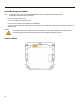
Laser Warnings and Labels Note: A 2D Imager Add-on may be installed on the Marathon. Laser warnings and labels that follow are specifically for a Marathon with a 2D Imager. l Do not look into the laser’s lens. l Do not stare directly into the laser beam. l Do not remove the laser caution labels from the Marathon. l Do not connect the laser bar code aperture to any other device. The laser bar code aperture is certified for use with the Marathon only. Caution Laser radiation when open.
Label 1-3
Components Front View Position Function 1-4 1 Status Indicators 2 Speakers 3 Touch Screen / Display 4 Microphone 5 Power Button 6 Biometric Mouse
Rear View Note: Extended battery is not attached in this image.
Bottom View Position Function 1 External Antenna Signal Pathway (for use in vehicle mount dock only) 2 Docking Connector (for use in desktop and vehicle mount docks) Right Side View The components are on the right side of the Marathon when viewed from the front. Position Function Note: 1-6 1 USB Port Cover 2 Reset Button 3 Two USB 2.0 Host Ports Caution. The Reset Button, when pressed in with the tip of the stylus, immediately disconnects all power sources.
Left Side View The components are on the left side of the Marathon when viewed from the front.
1-8
Chapter 2: Set Up A New Marathon This page lists a quick outline of the steps you might take when setting up a new Marathon. More instruction for each step is listed later in this guide. Please refer to the Marathon Reference Guide for additional information and instruction. Contact your representative if you need additional help. Note: Installing or removing accessories should be performed on a clean, well-lit surface.
Battery Charge or Recharge the Main Battery Note: A new Marathon must be connected to an external power source to charge the main battery before first use. The Marathon contains an internal Lithium Ion battery that, once fully charged, powers the Marathon for a minimum of 3 hours and 30 minutes (when the unit is not mounted in a powered dock or connected to an AC/DC adapter or extended battery). Note: An external power source is required before the main battery in the Marathon will recharge.
Tapping the Touchscreen with a Stylus Note: Always use the point of the stylus for tapping or making strokes on the touch screen. Never use an actual pen, pencil, or sharp/abrasive object to write on the touch screen. Hold the stylus as if it were a pen or pencil. Touch an element on the screen with the tip of the stylus then remove the stylus from the screen. Firmly press the stylus into the stylus holder when the stylus is not in use.
Using the Biometric Mouse The biometric mouse is located to the right of the keypad. Slide a finger over the biometric mouse to move the cursor in the direction the finger moves. Tapping the biometric mouse once generates a left-click, tapping twice rapidly generates a double-click. Tapping the biometric mouse and holding generates a right-click. Note: If experiencing difficulties with the biometric mouse navigation, try varying the finger pressure on the biometric mouse.
LED Indicators Power Button The power button is backlit as follows: l Off when not activated, Marathon is Off l Solid blue when activated, Marathon is On l Flashes blue when Marathon is in standby Status LEDs Status LED indicators are located next to the upper left hand corner of the display. Symbol Function Indicates the storage drive status: l LED flashes green when drive is accessed Indicates the wireless status: l LED is solid blue when enabled, but not connected.
Adjust Display Brightness The display can be lightened or darkened by using the Fn key and the keypad: 1. Hold the Fn key down for a few seconds until the Fn key remains illuminated (sticky). 2. Press the 9 (brightness up) key to brighten the display. 3. Press the 3 (brightness down) key to darken the display. The display brightness and darkness have nine levels. The display levels are managed by the Windows operating system.
Installing the Extended Battery Pack Note: Installing or removing accessories should be performed on a clean, well-lit surface. When necessary, protect the work surface, the Marathon, and components from electrostatic discharge. The instructions that follow are the same for the 42Whr extended battery and the 62Whr extended battery. 1. Turn the Marathon off. Remove any cables, straps or accessories. 2. Place the Marathon face down on a stable surface. 3.
5. Connect the extended battery to the Marathon using the captive screws in the extended battery. 6. Re-attach accessories, if any. 7. Turn the Marathon on. One extended battery can be recharged in a powered desktop dock (See Marathon Dock Reference Guide) and four extended batteries can be recharged in the Marathon Battery Charger (See Marathon Battery Charger User Guide). An attached extended battery will begin to recharge when the Marathon is placed in a powered desktop dock or powered vehicle dock.
Attaching the Hand Strap The hand strap is designed to be used with the Marathon with or without an extended battery attached. The hand strap is designed so the Marathon can be mounted in the desktop dock or the vehicle dock without removing the hand strap. 1. Long Hand Strap, approximately 7.4"/18.8 cm without loop 2. Short Hand Strap, approximately 4.0"/10.2 cm without loop 3. Strap Buckle 4. Screws, strap attaching 1. Place the Marathon with the screen facing down, on a flat stable surface. 2.
3. Remove any of the plugs by unscrewing them in a counter-clockwise direction. Remove only the plugs necessary to mount the hand strap. See the illustration below for possible hand strap orientations: Horizontal Vertical Diagonal 4. Insert the Strap Attaching Screws into the appropriate holes. These screws have an eye to attach the strap. 5. Thread the nylon loop of the Strap Buckle through one of the Strap Attaching Screws from the outside edge of the Marathon.
Attaching the Shoulder Strap The shoulder strap is designed to be used with the Marathon with or without an extended battery attached. The shoulder strap is designed so the Marathon can be mounted in the desktop dock or the vehicle dock without removing the shoulder strap. 1. Place the Marathon with the screen facing down, on a flat stable surface. 2. There are six rubber plugs as illustrated below (stars). 3. Remove the upper two of these plugs by unscrewing them in a counter-clockwise direction.
4. Insert the Strap Attaching Screws into the upper two holes. These screws have an eye to attach the strap. 5. Thread the longer nylon loop of one of the Shoulder Strap Adapters through one of the Strap Attaching Screws. Then thread the other end of the Shoulder Strap Adapter through the longer loop and pull tight. Repeat for the other Shoulder Strap Adapter using the other Strap Attaching Screw. 6. Hook the swivel hooks on each end of the Shoulder Strap to the short loops on the adapters.
Marathon Configuration Options Many configuration options are available via the Microsoft Windows Control panel. For additional information, please refer to Help and Support on the Start menu for configuration details. Date and Time Use the Windows interface to set date, time and time zone.
Restart/Shutdown Use the Windows interface to restart or shut down the Marathon. l Tap Start | Shut Down | Restart l Tap Start | Shut Down | Shut down Calibrate Touch Screen To calibrate the touch screen, tap Start | Programs | PenMount Universal Driver | Utility | PenMount Control Panel. Select PenMount 6000 USB and then tap Configure. Select Standard Calibration or Advance Calibration. Advanced Calibration allows the user to select the number of calibration points.
Marathon Desktop and Vehicle Dock The docks provide: l A mount for the Marathon computer. The desktop dock is located in a protected environment. The vehicle dock attaches to a vehicle via a RAM mount. l Conditioned power for the Marathon. The docks accept 12-24 VDC power input. l Connectors for an external monitor, four USB ports and an Ethernet connection are available when the Marathon is mounted in a powered desktop dock. The desktop dock also offers spare extended battery charging.
Using the Vehicle Dock 1. Attach RAM mount to vehicle (see Marathon Dock Guide). 2. Attach cabled accessories to dock. 3. Attach power cable. 4. Secure cables in the appropriate strain relief cable mounts. Place the Marathon in the Vehicle Dock Lower the Marathon into the docking bay until it is seated and then push it back into the dock. The release mechanisms will slide out of the way, and then spring forward, securing the Marathon in the vehicle dock.
Chapter 3: Connecting Cables to the Marathon Connecting USB Devices The Marathon provides two Type A USB ports behind the access door on the right side of the device. Open the port cover on the right side of the Marathon. Plug the desired device, such as a USB mouse or storage device, into the USB port. Refer to Start | Help and Support and the documentation for your USB device for more information. USB devices may be installed and removed or swapped without turning off the Marathon.
Connecting an AC/DC Power Supply Note: The Honeywell-approved AC Power Supply and Adapter Cable are only intended for use in a 25ºC (77ºF) maximum ambient temperature environment. 1. AC Input Cable (US only) 2. DC Output Cable 3. Power connector In North America, this unit is intended for use with power supply models FX1301PWRSPLY or FX1302PWRSPLY.
Connecting an Audio Device The Marathon provides an external headset connection via an audio jack connector under the left-hand port cover. Position Function 1 Power Connector / Audio Jack Cover 2 Audio Jack 3 Power Connector 1. Open the left-hand port cover. 2. Insert the speaker or headphone plug into the audio connector; making sure the plug is firmly seated in the jack. When the audio port is not in use, keep the port cover door closed.
Connecting a USB Tethered Scanner The Marathon accepts only USB tethered scanners. The scanner is connected to one of the USB ports on the right side of the Marathon. If the tethered scanner does not have it's own power supply, e.g. installed rechargeable battery, the tethered scanner draws power from the Marathon battery.
Connecting a Cigarette Lighter Power Adapter Note: The Honeywell-approved Cigarette Lighter cable is intended for use in 12V DC negative ground systems only. To view the instructions when using a cigarette lighter power adapter with a vehicle dock, please see the Marathon Dock Reference Guide. 1. Plug the lighter end of the cordset into an appropriate 12V DC automotive cigarette lighter receptacle. The LED on the cigarette lighter Power Adapter illuminates to indicate it is drawing power from the vehicle.
Connect Power Supply to Vehicle Mounted Dock Note: The vehicle cradle is designed for nominal 12V and 24V, negatively gounded vehicles only. 1. Align the connector pins to the vehicle dock Power port; firmly pushing the connector into the Power port. 2. Tighten the plug clockwise until the power cable is securely fastened. 3. Secure the cable to the dock with the installed strain relief cable clamp. The Power LED on the front of the vehicle dock illuminates when the dock is connected to vehicle power.
Chapter 4: Product Agency Compliance - Marathon Class B Digital Device FCC Rules, Part 15 This device complies with Part 15 of the FCC Rules [and with RSS-210 of Industry Canada]. Operation is subject to the following two conditions: 1. This device may not cause harmful interference, and 2. This device must accept any interference received, including interference that may cause undesired operation.
EMC Directive Requirements This is a Class B product. In a domestic environment this product may cause radio interference in which case the user may be required to take adequate measures. Industry Canada This Class B digital apparatus meets all requirements of the Canadian Interference Causing Equipment Regulations.
R&TTE Directive Requirements Dealer License - Republic of Singapore Republic of Singapore - LXE Dealer License Number DA103458 complies with IDA Standards.
Laser Light Safety Statement Warning: This product uses laser light. One of the following labels is provided on the scanner. Please read the Caution statement. (US) Mise én garde: Ce produit utilise un rayon laser. L’une des étiquettes suivantes est apposée sur le scanneur. Veuillez lire l’avertissement qu’elle contient. (FR) Advertência: Este produto usa luz de laser. O scanner contém um dos seguintes avisos. Favor ler o Aviso. (PT) Varning: Denna produkt använder laserljus.
4-5
Lithium Battery Safety Statement Caution: Lithium battery inside. Danger of explosion if battery is incorrectly replaced. Replace only with same or equivalent type recommended by battery manufacturer. (US) Attention: Contient une pile de lithium. Risque d’explosion dans le cas où la pile ne serait pas correctement remplacée. Remplacer uniquement avec une pile semblable ou equivalente au type de pile recommandé par le fabricant. (FR) Forsigtig: Indeholder lithiumbattterier.
Lithium Battery Safety Statement, continued Legend: Chinese – CN; Danish – DK; Dutch – NL; English – US; Finnish – FI; French- - FR; German – DE; Greek – GR; Italian – IT; Japanese – JP; Korean – KR; Norwegian – NO; Portuguese – PT; Spanish – ES; Swedish – SE; Turkish – TR.
Vehicle Power Supply Connection Safety Statement Vehicle Power Supply Connection: If the supply connection is made directly to the battery, a 10A slow-blow fuse should be installed in the positive lead within 5 inches (12.7 cm.) of the battery positive (+) terminal. (US) Raccordement de l’alimentation du véhicule Si l’alimentation est raccordée directement à la batterie, un fusible à action retardée de 10A doit être installé sur le câble positif à moins de 12,7 cm de la borne positive (+) de la batterie.
Chapter 5: Technical Assistance If you need assistance installing or troubleshooting your device, please contact us by using one of the methods below: Knowledge Base: www.hsmknowledgebase.com Our Knowledge Base provides thousands of immediate solutions. If the Knowledge Base cannot help, our Technical Support Portal (see below) provides an easy way to report your problem or ask your question. Product Service and Repair: www.honeywellaidc.com Honeywell International Inc.
Honeywell Scanning & Mobility 9680 Old Bailes Road Fort Mill, SC 29707 www.honeywellaidc.