
Installation Guide
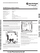
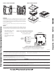

FIGURE 2. FACEPLATE INTERIOR:
BATTERY REPLACEMENT
Low battery levels on the wireless devices are displayed as a trouble in the FACP.
Therefore when the message “TROUBLE BATTERY LOW” is displayed, replace
the battery in the device. This message is an indication that approximately one week
of battery life remains.
COMPATIBILITY REQUIREMENTS
To ensure proper operation, this module shall be connected to a compatible Notifier
system control panel (list available from Notifier).
To replace the batteries in a wireless device use the following steps:
1. Have 4 CR123A (or DL123A) batteries available
2. Remove the faceplate from the module.
3. Open the battery compartment refer to Figure 3.
4. Remove the used batteries and replace with new batteries. The battery compart-
ment is designed such that the batteries can only align in the appropriate direction.
Do not force the batteries into the openings.
5. Replace the battery compartment cover.
6. Replace the faceplace.
SPECIFICATIONS
Maximum Operating Voltage: 3.3 VDC
Maximum Current Draw: 5.0 mA (LED on)
Average Operating Current: 210 µA, 3.9k EOL
EOL Resistance: 3.9K Ohms
Maximum IDC Wiring Resistance: 10 Ohms
Maximum IDC Voltage: 3.2 Volts
Maximum Average IDC Current: 5.5 µA
Maximum Transmit RF Power: 17 dBm
Radio Frequency Range: 902-928 MHz
Temperature Range: 32°F to 120°F (0°C to 49°C)
Humidity: 10% to 93% Non-condensing
Battery Type: 4 Panasonic CR123A or 4 Duracell DL123A
Battery Life: 2 year minimum
Battery Replacement: Upon TROUBLE BATTERY LOW display and/or during annual maintenance
Dimensions: 4¼ in. H x 4¼ in. W x 1½ in. D
Accessories: SMB500 Electrical Box (preferred mounting option)
BEFORE INSTALLING
This information is included as a quick reference installation guide. Refer to the con-
trol panel installation manual and the SLC Wireless Gateway Manual for detailed
system information. If the modules will be installed in an existing operational system,
inform the operator and local authority that the system will be temporarily out of ser-
vice. Disconnect power to the control panel before installing the modules.
NOTICE: This manual should be left with the owner/user of this equipment.
GENERAL DESCRIPTION
The FW-MM Monitor Module is intended for use with a wireless gateway or wire-
less fire alarm control panel (FACP) to interface with a device having contacts used
to signal status conditions. The input to the monitor module is non-latching and does
not require a reset. The device communicates through a robust, bi-directional mesh
network to the gateway and/or FACP. Rotary decade switches are provided for setting
the module’s address. The module has a panel controlled LED indicator. (Figure 1)
FIGURE 1. CONTROLS AND INDICATORS:
FACEPLATE
The faceplate includes a magnet for activation and tamper resistance (Figure 2). The
faceplate magnet activates communication to the panel, therefore, the faceplate must
be installed for the module to work properly. The magnet also activates a supervisory
tamper fault at the panel if the nameplate is removed. Do NOT remove this magnet.
The faceplate for a wireless module CANNOT be replaced with the faceplate of a
standard wired module.
NO-460-027 1 I56-4067-004
September 8, 2015
FW-MM Wireless Monitor Module
I56-4067-004
INSTALLATION AND MAINTENANCE INSTRUCTIONS
12 Clintonville Road
Northford, CT 06472-1653
Phone: 203.484.7161
MAGNET LOCA
TION
(DO NOT REMOVE)
C1095C-00
C1098-00