
Installation Guide

NO-460-027 2 I56-4067-004
September 8, 2015 ©2015 Notier
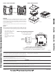
MOUNTING
The FW-MM mounts directly to an SMB500 electrical box (see Figure 4). To avoid
interference with the wireless network metal electrical boxes are NOT recommended.
Non-metal surface mounted electrical boxes (SMB500) are available from Notifier. If
not using an SMB500, the minimum mounting opening dimensions for the FW-MM
are 4 in. X 3¾ in. x 1½ in. deep.
NOTE: Do not attach the module to temporary structures such that the placement
could be altered.
WIRING
NOTE: All wiring must conform to applicable local codes, ordinances, and regula-
tions. This module is intended for power limited wiring only. FW-MM must be within
3 feet of monitored device when using field wiring or 20 feet in non-metallic conduit.
C1096-00
C1097-00
FIGURE 4. MODULE MOUNTING:FIGURE 3. BATTERY COMPARTMENT:
BATTERY
COMPARTMENT
DOOR
BATTERY
COMPARTMENT
C2002-00
This device complies with part 15 of the FCC Rules. Operation is subject to the following two conditions:
1. This device may not cause harmful interference, and
2. This device must accept any interference received, including interference that may cause undesired operation.
WARNING: Do not make changes to the equipment. Changes or modifications not expressly approved by the manufacturer could void the user’s authority to operate the equipment.
FCC STATEMENT
IC STATEMENT
This device complies with Industry Canada licence-exempt RSS standard(s). Operation is subject to the following two conditions: (1) this device may not cause interference, and (2) this device must accept any interference, includ-
ing interference that may cause undesired operation of the device.
RAPPORT D’IC
Le présent appareil est conforme aux CNR d’Industrie Canada applicables aux appareils radio exempts de licence. L’exploitation est autorisée aux deux conditions suivantes: (1) l’appareil ne doit pas produire de brouillage, et (2)
l’utilisateur de l’appareil doit accepter tout brouillage radioélectrique subi, même si le brouillage est susceptible d’en compromettre le fonctionnement
INSTITUTO FEDERAL DE TELECOMUNICACIONES
This device utilizes the Honeywell915 rev A radio module and complies with IFETEL standard(s). IFT: RCPHOSW14-1983
Use of these products in combination with non-Honeywell products in a wireless mesh network, or
to access, monitor or control devices in a wireless mesh nework via the internet or another external
wide area network, may require a separate license from Sipco, LLC. For more information, contact
Sipco, LLC or Ipco, LLC at 8215 Roswell Rd., Building 900, Suite 950, Atlanta, GA 303350, or
at www.sipocollc.com or www.intusiq.com.
LICENSING STATEMENT
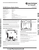
FIGURE 5. TYPICAL MONITORING CONFIGURATION:
WIRELESS
MONITOR MODULE
ONLY ONE UL LISTED CONTACT
CLOSURE MAY BE USED
POWER LIMITED
3.1 VDC MAX
3.9K EOL
RESISTOR
A2143-10
INSTALL CONTACT CLOSURE DEVICES PER
MANUFACTURER’S INSTALLATION INSTRUCTIONS.
WF-MM MUST BE WITHIN 3 FEET OF MONITORED DEVICE WHEN
USING FIELD WIRING OR 20 FEET IN NON-META LLIC CONDUIT.
C1099B-00
1. Install module wiring in accor-
dance with the job drawings and
appropriate wiring diagrams.
2. Set the address on the module per
job drawings.
3. Secure module to electrical box
(supplied by installer), as shown
in Figure 3.