
Installation Guide
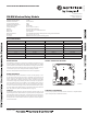

SPECIFICATIONS
Maximum Operating Voltage: 3.3 VDC
Maximum Current Draw: 5.0 mA (LED on)
Average Operating Current: 210uA
Maximum Transmit RF Power: 17dBm
Radio Frequency Range: 902-928 MHz
Temperature Range: 32°F to 120°F (0°C to 49°C)
Humidity: 10% to 93% Non-condensing
Battery Type: 4 Panasonic CR123A or 4 Duracell DL123A
Battery Life: 2 year minimum
Battery Replacement: Upon TROUBLE BATTERY LOW display and/or during annual maintenance
Dimensions: 4¼in. H x 4¼in. W x 1½in. D
Accessories: SMB500 Electrical Box (preferred mounting option)
BEFORE INSTALLING
This information is included as a quick reference installation guide. Refer to the con-
trol panel installation manual and the SLC Wireless Gateway Manual for detailed
system information. If the modules will be installed in an existing operational system,
inform the operator and local authority that the system will be temporarily out of ser-
vice. Disconnect power to the control panel before installing the modules.
NOTICE: This manual should be left with the owner/user of this equipment.
GENERAL DESCRIPTION
The FW-RM Relay Module is intended for use with a wireless gateway or wire-
less fire alarm control panel (FACP). It allows a compatible control panel to switch
discrete contacts by code command. The relay contains one isolated set of Form-C
contacts, which operate as a SPDT switch and are rated in accordance with the table
in this manual. A single relay module may be used to activate only one output device.
Two relay modules must be used in parallel to activate multiple devices such as a
NAC expander. Circuit connections to the relay are not supervised by the module.
The device communicates through a robust, bi-directional mesh network to the gate-
way and/or FACP. Rotary decade switches are provided for setting the module’s ad-
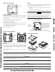
dress. The module has a panel controlled LED indicator. (Figure 1)
FACEPLATE
The faceplate includes a magnet for activation and tamper resistance (Figure 2). The
faceplate magnet activates communication to the panel, therefore, the faceplate must
be installed for the module to work properly. The magnet also activates a supervisory
tamper fault at the panel if the nameplate is removed. Do NOT remove this magnet.
The faceplate for a wireless module CANNOT be replaced with the faceplate of a
standard wired module.
NO-460-028 1 I56-4068-001
September 8, 2015
FW-RM Wireless Relay Module
I56-4068-001
INSTALLATION AND MAINTENANCE INSTRUCTIONS
12 Clintonville Road
Northford, CT 06472-1653
Phone: 203.484.7161
C1095B-00
RELAY CONTACT RATINGS:
CURRENT RATING MAXIMUM VOLTAGE LOAD DESCRIPTION APPLICATION
2 A 25 VAC PF = 0.35 Non-coded
3 A 30 VDC Resistive Non-coded
2 A 30 VDC Resistive Coded
0.46 A 30 VDC (L/R = 20ms) Non-coded
0.7 A 70.7 VAC PF = 0.35 Non-coded
0.9 A 125 VDC Resistive Non-coded
0.5 A 125 VAC PF = 0.75 Non-coded
0.3 A 125 VAC PF = 0.35 Non-coded
FIGURE 1. CONTROLS AND INDICATORS:
COMPATIBILITY REQUIREMENTS
To ensure proper operation, this module shall be connected to a compatible Notifier
system control panel (list available from Notifier).