
Installation Guide
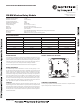

NO-460-028 2 I56-4068-001
September 8, 2015 ©2015 Notier
MOUNTING
The FW-RM mounts directly to an SMB500 electrical box (see Figure 4). To avoid
interference with the wireless network metal electrical boxes are NOT recommended.
Non-metal surface mounted electrical boxes (SMB500) are available from Notifier. If
not using an SMB500, the minimum mounting opening dimensions for the FW-RM
are 4 in. X 3¾ in. x 1½ in. deep.
NOTE: Do not attach the module to temporary structures such that the placement
could be altered.
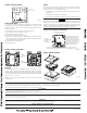
FIGURE 3. BATTERY COMPARTMENT:
BATTERY
COMPARTMENT
DOOR
BATTERY
COMPARTMENT
C2002-01
This device complies with part 15 of the FCC Rules. Operation is subject to the following two conditions:
1. This device may not cause harmful interference, and
2. This device must accept any interference received, including interference that may cause undesired operation.
WARNING: Do not make changes to the equipment. Changes or modifications not expressly approved by the manufacturer could void the user’s authority to operate the equipment.
FCC STATEMENT
IC STATEMENT
This device complies with Industry Canada licence-exempt RSS standard(s). Operation is subject to the following two conditions: (1) this device may not cause interference, and (2) this device must accept any interference, includ-
ing interference that may cause undesired operation of the device.
RAPPORT D’IC
Le présent appareil est conforme aux CNR d’Industrie Canada applicables aux appareils radio exempts de licence. L’exploitation est autorisée aux deux conditions suivantes: (1) l’appareil ne doit pas produire de brouillage, et (2)
l’utilisateur de l’appareil doit accepter tout brouillage radioélectrique subi, même si le brouillage est susceptible d’en compromettre le fonctionnement
INSTITUTO FEDERAL DE TELECOMUNICACIONES
This device utilizes the Honeywell915 rev A radio module and complies with IFETEL standard(s). IFT: RCPHOSW14-1983
BATTERY REPLACEMENT
Low battery levels on the wireless devices are displayed as a trouble in the FACP.
Therefore when the message “TROUBLE BATTERY LOW” is displayed, replace
the battery in the device. This message is an indication that approximately one week
of battery life remains.
To replace the batteries in a wireless device use the following steps:
1. Have 4 CR123A (or DL123A) batteries available
2. Remove the faceplate from the module.
3. Open the battery compartment refer to Figure 3.
4. Remove the used batteries and replace with new batteries. The battery compart-
ment is designed such that the batteries can only align in the appropriate direction.
Do not force the batteries into the openings.
5. Replace the battery compartment cover.
6. Replace the faceplace.
MAGNET LOCA
TION
(DO NOT REMOVE)
C1098-00
FIGURE 2. FACEPLATE INTERIOR: WIRING
NOTE: All wiring must conform to applicable local codes, ordinances, and regula-
tions. For applications interfacing with Emergency Control Functions, field wiring
shall be limited to 3' or 20' in non-metallic conduit.
1. Install module wiring in accordance with the job drawings and appropriate wir-
ing diagrams.
2. Set the address on the module per job drawings.
3. Secure module to electrical box (supplied by installer), as shown in Figure 4.
WARNING
All relay switch contacts are shipped in the standby state (open) state, but may have
transferred to the activated (closed) state during shipping. To ensure that the switch
contacts are in their correct state, modules must be made to communicate with the
panel before connecting circuits controlled by the module. When interfacing with an
emergency control function, that function must respond in 1 second or less.
Use of these products in combination with non-Honeywell products in a wireless mesh network, or
to access, monitor or control devices in a wireless mesh nework via the internet or another external
wide area network, may require a separate license from Sipco, LLC. For more information, contact
Sipco, LLC or Ipco, LLC at 8215 Roswell Rd., Building 900, Suite 950, Atlanta, GA 303350, or
at www.sipocollc.com or www.intusiq.com.
LICENSING STATEMENT
FIGURE 5. TYPICAL WIRING CONFIGURATION:
MODULE DOES NOT SUPERVISE
CONTROLLED CIRCUITS
IF ANY WIRING TO TERMINALS 1-4 IS
NONPOWER LIMITED, A NONPOWER
LIMITED LABEL MUST BE PLACED
OVER THE POWER LIMITED
TERMINAL
INFORMATION ON THE NAMEPLATE
LABEL. INSTALL CONTACT CLOSURE
DEVICES PER MANUFACTURER’S
INSTALLATION INSTRUCTIONS.
T1:
NOT USED
T2:
NORMALLY OPEN
T3:
COMMON
T4:
NORMALLY CLOSED
NOTE: IN APPLICATIONS INTERFACING WITH EMERGENCY CONTROL FUNCTIONS,
FIELD WIRING SHALL BE LIMITED TO 3 FEET OR 20 FEET IN NON-METALLIC CONDUIT.
C2019B-00
FIGURE 4. MODULE MOUNTING:
C1096-01