
Installation Instructions

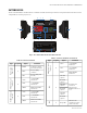
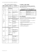
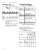
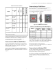
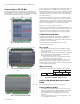
Table Of Contents

CPO-PC400-W/CPO-PC400-UW HVAC CONTROLLER
EN0B-0085 IE10 R0420 10
Connection to CP-IO Bus
The CPO-PC400-W/CPO-PC400-UW can communicate
with CP-EXPIO, CP-DIO and CPO-DIO modules through
the CP-IO Bus. See “Connection to a CP-IO Bus Powered by
the Separate Transformer” section on page 30.
Fig. 3. CP-EXPIO Dimensions (mm)
Fig. 4. CP-DIO Dimensions (mm)
Fig. 5. CPO-DIO Dimensions (mm)
A CP-IO bus can have a maximum of 16 modules. This can
be any combination of CP-EXPIO and CP-DIO modules.
Each CP-EXPIO module has a current consumption of 625
mA. The total current consumption of the max. number of
CP-EXPIO modules connected to one bus thus amounts to
16 x 625 mA = 10 A.
Each CP-DIO module has a current consumption of 625
mA. The total current consumption of the max. number of
CP-DIO modules connected to one bus thus amounts to 16
x 625 mA = 10 A (“Expansion I/O module” operating mode),
thus necessitating the use of a 12.5 A, time-lag fuse.
Fusing: See “Fusing” section on page 11.
Each CP-DIO module features an integrated termination
resistor which the user must set using the mode switch. For
more information on CP-EXPIO, CP-DIO and CPO-DIO
modules, see “Technical Literature” section on page 40.
Connection to M-Bus
The CPO-PC400-W/CPO-PC400-UW can communicate
with M-Bus through a level converter e.g. PW60 from
company Relay GmbH. See “Connection to M-Bus via Level
Converter” section on page 32.
A maximum number of 60 M-Bus devices can be
connected to a controller.
Bus Length
• Max. M-Bus length: 350 meters from PW60, at baud
rates of 9.6 k baud or slower with shielded pair cable: J-
Y-(St)-Y 2 x 2 x 0,8.
• The M-Bus can be extended to 1,000 meters, depending
upon the baud rate and provided that the following
electrical limitations are observed:
— Bus voltage must be at no point fall below 12 Vdc.
— Max. cable capacitance of 180 nF.
For bus length extension, M-Bus repeaters can be used,
but have not been tested by Honeywell. Hence, it is the
responsibility of the installing / commissioning personnel
to ensure proper functioning.
Wiring Topology
M-Bus meters are connected to the bus cable in parallel.
Fig. 6. Allowed M-Bus wiring topology
Cabling CPO-PC400-W/CPO-PC400 to
PW60
See “Cable Specifications” section on page 14.
Cabling PW60 to M-Bus
• Use shielded, twisted pair cable J-Y-(St)-Y 2 x 2 x 0,8.
• Shielding is especially recommended when the M-Bus
cable is installed in areas with expected or actual
electromagnetic noise. Avoiding such areas is to be
preferred.
• Connect the shield to a noise-free earth ground – only
once per M-Bus connection.
CPO-PC400 PW Conveter
SLAVE 1 SLAVE 2 SLAVE 3