
Installation Instructions

IO-10MIXR-WE / IO-10MIXR-NWE SMART IO
31-00427 | Rev.10-20 4
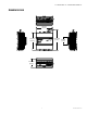
NOTES:
— Ethernet Ports are for Future Use
— USB-C Port is for Future Use.
— Wi-Fi 5 GHz is for Future Use.
— The GNDs for the UIO and DI are intercon-
nected.
— Refer to 31-00429(SmartIO Installation
Instructions) for terminal wiring.
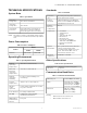
Change-over
Relay 1
16 NO1
Normally Open
contact
17 COM
COM contact for
Relay 1
18 NC1
Normally Closed
contact
Change-over
Relay 2
19 NO2
Normally Open
contact
20 COM
COM contact for
Relay 2
21 NC2
Normally Closed
contact
Change-over
Relay 3
22 NO3
Normally Open
contact
23 COM
COM contact for
Relay 3
24 NC3
Normally Closed
contact
Change-over
Relay 4
25 NO4
Normally Open
contact
26 COM
COM contact for
Relay 4
27 NC4
Normally Closed
contact
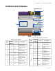
RJ45
Interface
28
Ethernet
1
10/100 base-T/TX
Ethernet
2
SMA
Connector
29
Wi-Fi
and
Bluetooth
antenna
Antenna for both
Wi-Fi and
Bluetooth
802.11a/b/g/n/ac
+ BT 4.2
Reset/Wireless
Button
30
Bluetooth
/Factory
reset
button
Physical button to
activate Bluetooth
or reset the device
to factory default.
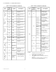
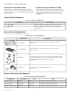
Table 3. Device Terminals (Continued)
Type
Termina
l
Number
Signal Description
USB-C
31
USB-C port to
connect with
laptops, mobile,
and tablets for
initial firmware
upgrade.
LED
32
UIO 1 Transmit and
receive indication
of Universal
Input/Output
(Off, Green, Yellow,
and Red)
UIO 2
UIO 3
UIO 4
DI 1 Status indication
of Digital input
(Off, Green, Yellow,
and Red)
DI 2
DO 1
Relay status of
Digital output
(Off and Green)
DO 2
DO 3
DO 4
33 Wi-Fi
Indicates
operational status
of the Wi-Fi
(Off, Green, Yellow,
and Red)
34 Bluetooth
Indicates
operational status
of the Bluetooth
(Off, Green, Yellow,
and Red)
35 Main LED
Indicates the
operational status
of the Smart IO
(Off, Green, Yellow,
and Red)
Table 3. Device Terminals (Continued)
Type
Termina
l
Number
Signal Description