
Overview of Primary Product


V48A,F,J; V88A,J DIAPHRAGM GAS VALVES
11 60-2080—9
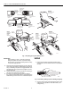
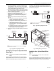
Fig. 13. Internal view of actuator housing.
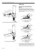
Fig. 14. Coil assembly fits on plunger tube assembly.
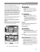
Fig. 15. Coil assembly, insulator, and cover.
CAUTION
Equipment Damage Hazard.
Operation without proper checkout can damage
the equipment.
1. Do not put the system into service until you have
satisfactorily completed the following Valve Leak
Test, all applicable tests described in the Checkout
section of the Instructions for the flame safeguard
control, and any other tests required by the burner
manufacturer.
2. All tests must be performed by a trained,
experienced flame safeguard control technician.
3. Close all manual fuel shutoff valves as soon as
trouble occurs.
After the installation is complete, cycle the valve several times
with the manual fuel shutoff cock closed. Make sure the valve
and actuator function properly. Also perform the Valve Leak
Test that follows before putting the valve into service.
Valve Leak Test (Fig. 7)
This is a test for checking the closure tightness of a gas
safety shutoff valve. It should be performed by qualified
personnel during the initial startup of a burner system, or
whenever the valve or valve bonnet is replaced (see
Service Information section). It is recommended that this
test also be included in the scheduled inspection and
maintenance procedures. For a periodic inspection test,
follow steps 1, 3, 4, 5, 8, 9, 10, 12, 13, 16, and 17.
M7301
HOLDING NUT
COIL ASSEMBLY
GROUNDING
SCREW
2 TORX 20
SCREWS HOLDING
ACTUATOR HOUSING
ACTUATOR
HOUSING
COIL ASSEMBLY
PLUNGER TUBE
ASSEMBLY
M7303
WRAPAROUND
METAL COVER
M7304
BLACK LEADWIRES
METAL BASE
CARDBOARD
INSULATOR
COIL
ASSEMBLY
CARDBOARD
INSULATOR
HOOKED TOGETHER