
Overview of Primary Product


V48A,F,J; V88A,J DIAPHRAGM GAS VALVES
5 60-2080—9
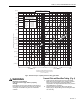
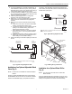
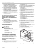
Fig. 2. Pressure drop vs. capacity chart for sizing gas valves.
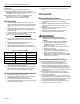
WARNING
Explosion or Fire Hazard.
Can cause severe injury, death or property
damage.
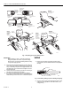
If the flow is not in the same direction as the arrow on
the bottom of the gas valve, the valve may not shut off,
causing an accumulation of gas in the combustion
chamber.
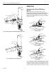
Connect Pilot and Bleed Gas Tubing (Fig. 4)
1. Square off and remove burrs from end of the tubing.
Bend tubing to the desired form for routing to the pilot
burner. Do not bend tubing at the valve after the
compression nut is tightened because this may result in
gas leakage at the connection.
2. Unscrew brass compression fitting from pilot gas
tapping (Fig.4). Slip the fitting over the tubing and slide
out of the way.
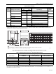
PRESSURE DROP VS. CAPACITY
FOR 0.64 SP GR. GAS
A.G.A.RATING FOR
0.64 SP. GR. GAS AT
1 IN. PRESSURE DROP
VALVE SIZE CAPACITY
3/4 IN.
1 IN.
1-1/4 IN.
1-1/2 IN.
2 IN.
2-1/2 IN.
3 IN.
668 cf/h
1021 cf/h
2100 cf/h
2400 cf/h
4178 cf/h
5100 cf/h
5562 cf/h
3/4
1
1-1/4
1-1/2
2
2-1/2
3
1 1.5 2 2.5 3 4 5 6 7 8 9 10 1.5 2 2.5 3 4 5 6 7 8 9 10
MULTIPLY BY 100
MULTIPLY BY 1000
[0.025] 0.1
0.15
[0.05] 0.2
0.25
[0.075] 0.3
[0.1] 0.4
0.5
[0.15] 0.6
0.7
[0.2] 0.8
0.9
[0.25] 1.0
1.5
[0.5] 2
2.5
[0.75] 3
[1.0] 4
5
[1.5] 6
7
[2.0] 8
9
[2.5] 10
M8491
PRESSURE DROP—INCHES W.C. [kPa]
CAPACITY IN CUBIC FEET PER HOUR (cf/h)
FOR GAS WITH SPECIFIC GRAVITY OF 0.64
[1 cf/h = 0.0283 m
3
/hr]