
Overview of Primary Product


V48A,F,J; V88A,J DIAPHRAGM GAS VALVES
60-2080—9 8
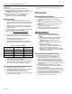
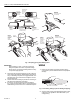
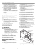
Fig. 8. Installing optional 126590 adjustable bleed valve.
Fig. 9. Installing optional bleed orifice.
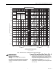
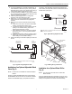
OPERATION
Operation of the V48 and V88 Valves
(Fig. 10)
When the controller is not calling for heat, the coil is
de-energized. The plunger in the 3-way actuator is in the
DOWN position so the bleed port is closed and the supply port
is open. Gas flows into the top part of the valve. The gas
pressure on top of the diaphragm, the weight, and the spring
hold the valve closed.
Fig. 10. Operation of V48 and V88 diaphragm gas valves.
On a call for heat, the controller contacts close and the coil is
energized. This pulls the plunger to the UP position, opening
the bleed port and closing the supply port. The gas in the top
BLEED TAPPING
126590 ADJUSTABLE BLEED VALVE
SLEEVE
COMPRESSION NUT
1/4 INCH
TUBING
7/16-24 UNS
ADJUSTING SCREW
7/16 INCH HEX
1/8-27 NPT
M7290
BLEED PORT
1/8-27 NPT
M7298A
1/8 INCH DIAMETER ROD
BLEED ORIFICE
(SELECTED)
GAS
SUPPLY
PASSAGE
BLEED
PORT
PLUNGER
SPRING
WEIGHT
DIAPHRAGM
MAIN
GAS
SUPPLY
TO BURNER
VALVE CLOSED
GAS
SUPPLY
PASSAGE
BLEED
PORT
PLUNGER
SPRING
WEIGHT
DIAPHRAGM
MAIN
GAS
SUPPLY
TO BURNER
VALVE OPENING
GAS
SUPPLY
PASSAGE
BLEED
PORT
PLUNGER
SPRING
WEIGHT
DIAPHRAGM
MAIN
GAS
SUPPLY
TO BURNER
VALVE OPEN
M8489