
Overview of Primary Product
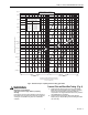

V48A,F,J; V88A,J DIAPHRAGM GAS VALVES
7 60-2080—9
3. For normal installations, use moisture-resistant No. 14
wire suitable for at least 167°F (75°C) if using a flame
safeguard primary control, or for at least 194°F (90°C) if
using a flame safeguard programming control.
4. For high temperature installation, use moisture-resistant
No. 14 wire selected for a temperature rating above the
maximum operating temperature.
5. Check the power supply circuit. The voltage and
frequency must match those of the valve.
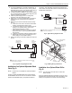
6. Refer to Fig. 5 or 6 for typical field wiring connections.
Follow the burner manufacturers wiring diagram if
provided.
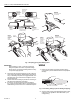
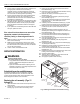
7. Make wiring connections inside the actuator housing
(Fig. 7):
a. Loosen the cover screw in the front of the actuator
housing, and remove the housing cover.
b. If a conduit is required, run the conduit through the
opening in the actuator housing, and run the
external wires through the conduit.
c. Using solderless connectors, connect the external
wires to the two 6 in. (152.4 mm) black leadwires
(from the coil).
d. Locate the connections inside the actuator housing.
e. Replace the housing cover, and tighten the cover
screw holding it to the actuator housing.
8. Recheck the wiring circuits before putting the valve into
service.
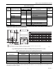
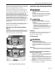
Fig. 5. Typical wiring diagram for V48.
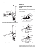
Installation of an Optional Adjustable Bleed
Valve (Fig. 8).
NOTE: This device is not available for valves with BSP.PI
threads.
Screw the 126590 Adjustable Bleed Valve into the tapping
marked BLEED. Be sure to screw the end with the 1/8-NPT
threads into the BLEED tapping. Complete the bleed line
connection. Then alternately energize and de-energize the
valve actuator, and adjust the screw on the bleed valve for the
desired valve opening time.
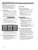
Fig. 6. Typical wiring diagram for V88.
Fig. 7. Making wiring connections.
Installation of an Optional Bleed Orifice
(Fig. 9)
NOTE: The orifice tool cannot be used on valves with
BSP.PI threads.
Press the selected bleed orifice (see Table 2) over the 1/8 in.
diameter dowel and press until the orifice cup bottoms in the
bleed port. Complete the connection of the bleed tubing.
M8490A
VALVE ACTUATOR
(BLACK LEAD WIRES)
FLAME
SAFEGUARD
CONTROL
L1
(HOT)
L2
1
1
POWER SUPPLY. PROVIDE DISCONNECT MEANS AND OVERLOAD
PROTECTION AS REQUIRED.
LIMIT(S)
LINE VOLTAGE
THERMOSTAT OR
CONTROLLER
M8488A
LIMIT(S)
V88
VALVE ACTUATOR
(BLACK LEAD WIRES)
24 VOLT
THERMOSTAT
24V
FLAME
SAFEGUARD
CONTROL
TRANSFORMER
L1
(HOT)
L2
1
1
POWER SUPPLY. PROVIDE DISCONNECT MEANS AND OVERLOAD
PROTECTION AS REQUIRED.
M7302
6 IN. [152.4 MM] INTERNAL
BLACK LEADWIRES
(FROM COIL)
SOLDERLESS
CONNECTORS
GROUNDING
SCREW
EXTERNAL
WIRES
ACTUATOR
HOUSING
OPENING IN
ACTUATOR
HOUSING
CONDUIT
(IF REQUIRED)
COVER
SCREW