Voyager™ 1200g/1202g Single-Line Laser Bar Code Scanner User’s Guide
Disclaimer Honeywell International Inc. (“HII”) reserves the right to make changes in specifications and other information contained in this document without prior notice, and the reader should in all cases consult HII to determine whether any such changes have been made. The information in this publication does not represent a commitment on the part of HII.
Product Agency Compliance - Voyager 1200g USA FCC Part 15 Subpart B Class B This device complies with part 15 of the FCC Rules. Operation is subject to the following two conditions: 1. This device may not cause harmful interference. 2. This device must accept any interference received, including interference that may cause undesired operation. This equipment has been tested and found to comply with the limits for a Class B digital device pursuant to part 15 of the FCC Rules.
Europe The CE marking indicates compliance with the following directives: • 2004/108/EC EMC • 2011/65/EU RoHS (Recast) In addition, complies to 2006/95/EC Low Voltage Directive, when shipped with recommended power supply. European contact: Hand Held Products Europe B.V. Nijverheidsweg 9-13 5627 BT Eindhoven The Netherlands Honeywell International Inc. shall not be liable for use of our product with equipment (i.e., power supplies, personal computers, etc.
CB Scheme Certified to CB Scheme IEC 60950-1, Second Edition. Laser Safety Statement LASER LIGHT: DO NOT STARE INTO BEAM. CLASS 2 LASER PRODUCT. LASERSTRAHLUNG: NICHT IN DEN STRAHL BLICKEN. LASER KLASSE 2. LUMIERE LASER: NE PAS REGARDER DANS LE FAISCEAU. APPAREIL A LASER. DE CLASSE 2 630-650nm, 1mW. This device has been tested in accordance with and complies with IEC60825-1 ed2.0 and 21 CFR 1040.10 and 1040.11, except for deviations pursuant to Laser Notice No. 50, dated June 24, 2007.
Product Agency Compliance - Voyager 1202g and CCB00-010BT USA FCC Part 15 Subpart C This device complies with part 15 of the FCC Rules. Operation is subject to the following two conditions: 1. This device may not cause harmful interference. 2. This device must accept any interference received, including interference that may cause undesired operation. Caution: Any changes or modifications made to this equipment not expressly approved by Honeywell may void the FCC authorization to operate this equipment.
Honeywell Scanning & Mobility Product Environmental Information Refer to www.honeywellaidc.com/environmental for the RoHS / REACH / WEEE information. Australia/NZ C-Tick Statement Conforms to AS/NZS 3548 EMC requirements. China SRRC Radio Certificate. CCC safety (CCB00-010BT base only) Japan Complies with Technical Regulations Conformity Certification of Specified Radio equipment. Korea This product meets Korean agency approval.
International LED Safety Statement LEDs have been tested and classified as “EXEMPT RISK GROUP” to the standard: IEC 62471:2006. Radio Technology Class II CB Scheme Certified to CB Scheme IEC 60950-1, Second Edition. Laser Safety Statement LASER LIGHT: DO NOT STARE INTO BEAM. CLASS 2 LASER PRODUCT. LASERSTRAHLUNG: NICHT IN DEN STRAHL BLICKEN. LASER KLASSE 2. LUMIERE LASER: NE PAS REGARDER DANS LE FAISCEAU. APPAREIL A LASER. DE CLASSE 2 630-650nm, 1mW.
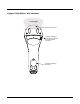
Voyager 1200g Safety Label Locations Laser Output Internal Laser Cautions Compliance Markings information, Part Number, and Serial Number information Compliance Markings information
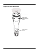
Voyager 1202g Safety Label Locations Laser Output Internal Laser Cautions Laser Safety Information Compliance Markings information, Part Number, and Serial Number information Compliance Markings information
CCB00-010BT Safety Label Locations Item Number, Serial Number, and Compliance Markings information Compliance Markings information
Table of Contents Chapter 1 - Getting Started About This Manual ...............................................................................................................1-1 Unpacking Your Device .......................................................................................................1-1 Connecting the Device .........................................................................................................1-1 Connecting with USB ....................................................
Keyboard Wedge Modifiers ............................................................................................... 2-18 ALT Mode .................................................................................................................... 2-18 Keyboard Style ............................................................................................................ 2-18 Keyboard Conversion ..................................................................................................
Flash Updates ..................................................................................................................... 3-4 Beeper and LED Sequences and Meaning ......................................................................... 3-4 Scanner LED Sequences and Meaning......................................................................... 3-5 Base LED Sequences and Meaning.............................................................................. 3-5 Base Power Communication Indicator...
Good Read and Error Indicators.......................................................................................... 4-1 Beeper – Good Read..................................................................................................... 4-1 Beeper Volume – Good Read........................................................................................ 4-2 Beeper Pitch – Good Read............................................................................................ 4-2 Beeper - Transmit Order.
Prefix Selections.................................................................................................................. 5-2 Suffix Selections .................................................................................................................. 5-3 Transmit Alternate Extended ASCII Characters .................................................................. 5-3 Function Code Transmit ....................................................................................................
UPC-E0 ............................................................................................................................. 7-30 EAN/JAN-13 ...................................................................................................................... 7-33 Convert UPC-A to EAN-13 .......................................................................................... 7-33 ISBN Translate ........................................................................................................
Standard Cable Pinouts..................................................................................................... 11-5 Keyboard Wedge ......................................................................................................... 11-5 Serial Output ............................................................................................................... 11-5 RS485 Output .............................................................................................................
viii
1 Getting Started About This Manual This User’s Guide provides installation and programming instructions for the Voyager 1200g/1202g linear scanner. Product specifications, dimensions, warranty, and customer support information are also included. Honeywell bar code scanners are factory programmed for the most common terminal and communications settings. If you need to change these settings, programming is accomplished by scanning the bar codes in this guide.
2. Make sure the cables are secured in the wireways in the bottom of the base and that the base sits flat on a horizontal surface. 3. The scanner beeps. 4. Verify the scanner or base operation by scanning a bar code from the Sample Symbols in the back of this manual. The unit defaults to a USB PC Keyboard. Refer to page 2-4 for other USB terminal settings. For additional USB programming and technical information, refer to “USB Application Note,” available at www.honeywellaidc.com.
5. Verify the scanner or base operation by scanning a bar code from the Sample Symbols in the back of this manual. The scanner beeps once. The unit defaults to an IBM PC AT and compatibles keyboard wedge interface with a USA keyboard. A carriage return (CR) suffix is added to bar code data. Connecting with RS232 Serial Port 1. Turn off power to the terminal/computer. 2. Connect the appropriate interface cable to the scanner.
Connecting with RS485 A scanner or base can be connected for an IBM POS terminal interface. 1. Connect the appropriate interface cable to the device, then to the computer. Charge and Communications Base RS485 Connection: 2. Make sure the cables are secured in the wireways in the bottom of the base and that the base sits flat on a horizontal surface. 3. Turn the terminal/computer power back on. The scanner beeps. 4.
Reading Techniques The scanner has a view finder that projects a bright red aiming beam that corresponds to the scanner’s horizontal field of view. The aiming beam should be centered horizontally over the bar code and must highlight all the vertical bars of the bar code. It will not read if the aiming beam is in any other direction. Good Read Bad Read The aiming beam is smaller when the scanner is closer to the code and larger when it is farther from the code.
Resetting the Custom Defaults If you want the custom default settings restored to your scanner, scan the Activate Custom Defaults bar code below. This resets the scanner to the custom default settings. If there are no custom defaults, it will reset the scanner to the factory default settings. Any settings that have not been specified through the custom defaults will be defaulted to the factory default settings.
2 Programming the Interface Introduction This chapter describes how to program your system for the desired interface. Programming the Interface - Plug and Play Plug and Play bar codes provide instant scanner set up for commonly used interfaces. Note: After you scan one of the codes, power cycle the host terminal to have the interface in effect. Keyboard Wedge If you want your system programmed for an IBM PC AT and compatibles keyboard wedge interface with a USA keyboard, scan the bar code below.
IBM Port 9B HHBCR-1 Interface IBM Port 17 Interface IBM Port 9B HHBCR-2 Interface Each bar code above also programs the following suffixes for each symbology: Symbology Suffix Symbology Suffix EAN 8 EAN 13 UPC A UPC E 0C 16 0D 0A Code 39 Interleaved 2 of 5 Code 128 * Code 128 ** 00 00 00 00 0A 0D 0A 18 0B 0B 0B 0B * Suffixes programmed for Code 128 with IBM 4683 Port 5B, IBM 4683 Port 9B HHBCR-1, and IBM 4683 Port 17 Interfaces **Suffixes programmed for Code 128 with IBM 4683 Port 9 HHBCR-2 Int
OPOS Mode USB IBM SurePos Scan one of the following “Plug and Play” codes to program the scanner for an IBM SurePos (USB handheld scanner) or IBM SurePos (USB tabletop scanner) interface. Note: After scanning one of these codes, you must power cycle the cash register.
USB PC or Macintosh Keyboard Scan one of the following codes to program the scanner for USB PC Keyboard or USB Macintosh Keyboard. Scanning these codes also adds a CR and LF. USB Keyboard (PC) USB Keyboard (Mac) USB Japanese Keyboard (PC) USB HID Scan the following code to program the scanner for USB HID bar code scanners.
Scanning either of these codes also adds a CR and LF. USB Serial Emulation for Windows XP, Windows Server 2003, and later USB Serial Emulation for Windows 2000 Note: No extra configuration (e.g., baud rate) is necessary. CTS/RTS Emulation CTS/RTS Emulation On * CTS/RTS Emulation Off ACK/NAK Mode ACK/NAK Mode On * ACK/NAK Mode Off Communication Timeout This allows you to set the length (in milliseconds) for a timeout for the host ACK/NAK response.
Timeout Retries This setting limits the number of Communication Timeout retries. If the Timeout Retries is set to 0, the transmission is terminated after the initial Communication Timeout. Scan the bar code below, then set the number of retries (from 0255) by scanning digits from the Programming Chart, then scanning Save. (5 is the recommended setting.) Default = 0.
Verifone® Ruby Terminal Default Settings Scan the following Plug and Play code to program the scanner for a Verifone Ruby terminal. This bar code sets the baud rate to 1200 bps and the data format to 8 data bits, Mark parity, 1 stop bit and RTS/CTS no timeout.
Datalogic™ Magellan© Bioptic Aux Port Configuration Scan the following Plug and Play code to program the scanner for a Datalogic Magellan bioptic scanner auxiliary port configuration. This bar code sets the baud rate to 9600 bps and the data format to 8 data bits, no parity, 1 stop bit. Datalogic Magellan Bioptic Settings Note: If you are having unexpected results with this programming code, scan the Resetting the Custom Defaults bar code on page 1-6 first, then scan the programming code above.
Wincor Nixdorf Beetle™ Terminal Default Settings Scan the following Plug and Play code to program the scanner for a Wincor Nixdorf Beetle terminal.
Keyboard Countries (Continued) Albania Arabic Azeri (Cyrillic) Azeri (Latin) Belarus Belgium Bosnia Brazil Brazil (MS) Bulgaria (Cyrillic) Bulgaria (Latin) 2 - 10
Keyboard Countries (Continued) Canada (French legacy) Canada (French) Canada (Multilingual) China Croatia Czech Czech (Programmers) Czech (QWERTY) Czech (QWERTZ) Denmark Dutch (Netherlands) 2 - 11
Keyboard Countries (Continued) Estonia Faroese Finland France Gaelic Germany Greek Greek (220 Latin) Greek (220) Greek (319 Latin) Greek (319) 2 - 12
Keyboard Countries (Continued) Greek (Latin) Greek (MS) Greek (Polytonic) Hebrew Hungarian (101 key) Hungary Iceland Irish Italian (142) Italy Japan ASCII 2 - 13
Keyboard Countries (Continued) Korea Kazakh Kyrgyz (Cyrillic) Latin America Latvia Latvia (QWERTY) Lithuania Lithuania (IBM) Macedonia Malta Mongolian (Cyrillic) 2 - 14
Keyboard Countries (Continued) Norway Poland Polish (214) Polish (Programmers) Portugal Romania Russia Russian (MS) Russian (Typewriter) SCS Serbia (Cyrillic) 2 - 15
Keyboard Countries (Continued) Serbia (Latin) Slovakia Slovakia (QWERTY) Slovakia (QWERTZ) Slovenia Spain Spanish variation Sweden Switzerland (French) Switzerland (German) Tatar 2 - 16
Keyboard Countries (Continued) Thailand Turkey F Turkey Q Ukrainian United Kingdom United States (Dvorak) United States (Dvorak left) United Stated (Dvorak right) United States (International) Uzbek (Cyrillic) Vietnam 2 - 17
Keyboard Wedge Modifiers ALT Mode If your bar code contains special characters from the extended ASCII chart for example, an e with an accent grave (è), you will use ALT Mode. (See "Extended ASCII Characters" on page A-4.) Note: Scan the ALT mode bar code after scanning the appropriate Keyboard Country code. If your keystrokes require using the ALT key and 3 characters, scan the 3 Characters bar code. If your keystrokes require the ALT key and 4 characters, scan the 4 Characters bar code.
Autocaps via NumLock bar code should be scanned in countries (e.g., Germany, France) where the Caps Lock key cannot be used to toggle Caps Lock. The NumLock option works similarly to the regular Autocaps, but uses the NumLock key to retrieve the current state of the Caps Lock. Autocaps via NumLock Emulate External Keyboard should be scanned if you do not have an external keyboard (IBM AT or equivalent).
Default = Control + ASCII Mode Off. Windows Mode Control + ASCII Mode On * Control + ASCII Mode Off DOS Mode Control + ASCII Mode On Windows Mode Prefix/Suffix Off Numeric Keypad Mode: Sends numeric characters as if entered from a numeric keypad. Default = Off. Numeric Keypad Mode On * Numeric Keypad Mode Off Inter-Scan Code Delay When your keyboard detects that any key is being pressed, released, or held down, the keyboard sends a packet of information known as a “scan code” to your computer.
Break Character When your keyboard detects that any key is being pressed, released, or held down, the keyboard sends a packet of information known as a “scan code” to your computer. There are two different types of scan codes: “make codes” and “break codes.” A make code is sent when a key is pressed or held down. A break code is sent when a key is released. The following selections allow you to suppress or transmit the character sequence of the break code. Default = Transmit.
RS232 Modifiers RS232 Baud Rate Baud Rate sends the data from the scanner to the terminal at the specified rate. The host terminal must be set for the same baud rate as the scanner. Default = 9600.
RS232 Word Length: Data Bits, Stop Bits, and Parity Data Bits sets the word length at 7 or 8 bits of data per character. If an application requires only ASCII Hex characters 0 through 7F decimal (text, digits, and punctuation), select 7 data bits. For applications that require use of the full ASCII set, select 8 data bits per character. Default = 8. Stop Bits sets the stop bits at 1 or 2. Default = 1. Parity provides a means of checking character bit patterns for validity. Default = None.
7 Data, 2 Stop, Parity Space 8 Data, 1 Stop, Parity Space 7 Data, 1 Stop, Parity Mark 7 Data, 2 Stop, Parity Mark 8 Data, 1 Stop Parity Mark RS232 Handshaking RS232 Handshaking allows control of data transmission from the scanner using software commands from the host device. RTS/CTS Off: RTS/CTS is turned off so no data flow control is used, but RTS is still active. RTS/CTS Off, RTS Inactive: RTS/CTS is turned off so no data flow control is used and RTS is inactive.
Flow Control, No Timeout Character-Based Flow Control, No Timeout Two-Direction Flow Control Flow Control with Timeout Character-Based Flow Control with Timeout RS232 Timeout When using Flow Control with Timeout, you must program the length of the delay you want to wait for CTS from the host. Set the length (in milliseconds) for a timeout by scanning the bar code below, then setting the timeout (from 1-5100 milliseconds) by scanning digits from the Programming Chart, then scanning Save.
ACK/NAK After transmitting data, the scanner waits for an ACK character (hex 06) or a NAK character (hex 15) response from the host. If ACK is received, the communications cycle is completed and the scanner looks for more bar codes. If NAK is received, the last set of bar code data is retransmitted and the scanner waits for ACK/NAK again. Turn on the ACK/NAK protocol by scanning the ACK/NAK On bar code below. To turn off the protocol, scan ACK/NAK Off. Default = ACK/NAK Off.
NAK Retries This selection limits the number of NAK retries that can occur in ACK/NAK mode. Scan the bar code below, then set the number of retries (from 0-255) by scanning digits from the Programming Chart, then scanning Save. (5 is the recommended setting.) Default = 0, or disabled. NAK Retries Support BEL/CAN in ACK/NAK This protocol responds to and commands when in ACK/NAK mode. The scanner sounds an error tone when a command is sent from the host. terminates the transmission.
Block Check Character When this selection is set to Transmit, the NCR Block Check Character (BCC) is expected with incoming messages and transmitted with outgoing messages. Default = Transmit. * Transmit Don’t Transmit NCR Prefix This selection allows you to program an NCR-specific prefix. Refer to the ASCII Conversion Chart (Code Page 1252), page A-2 to find the hex equivalent for the characters you want for the NCR prefix (typically, 02 for STX).
NCR NOF (Not-on-File) Error A scanner receives an NOF (Not on File) command from the POS whenever it cannot cross-reference the bar code to a price parameter. When set to On, the error tone sounds (set via Number of Beeps – Error, page 4-3) for an NOF, and disables the scanner while the cashier looks up the price manually. When set to Off, no sound is emitted for an NOF. Default = Off.
Communication Timeout This allows you to set the length (in milliseconds) for a timeout for the host ACK/NAK response. Scan the bar code below, then set the timeout (from 1-65535 milliseconds) by scanning digits from the Programming Chart, then scanning Save. Default = 2000 ms.
3 Cordless System Operation Note: This chapter applies only to cordless scanning systems. It does not apply to corded scanners. How the Charge and Communications Base Works A cordless charge and communications base provides the link between the cordless scanner and the host system. The base contains an interface assembly and an RF communication module. The RF communication module performs the data exchange between the cordless scanner and the interface assembly.
When data is scanned, the data is sent to the host system via the base. The cordless scanner recognizes data acknowledgement (ACK) from the base. If it cannot be determined that the data has been properly sent to the base, the scanner issues an error indication. You must then check to see if the scanned data was received by the host system.
You will not hear a communication error tone in this mode, but you will hear a short buzz when you press the button if the radio communication is not working. Once the radio connection is made, the scanner produces a series of beeps while the data is being transferred to the base. Page Button When you press the Page button on the base, the scanner associated with that base will begin beeping (3 short and 1 long beep).
Place the scanner in the base that is connected to an appropriate power supply. Use only a Listed Limited Power Source (LPS) or Class 2 type power supply with output rated 5 to 5.2Vdc, 1A. Note: If you are powering the base through the interface cable (for example, a USB cable) and not using an external power supply plugged into the aux port, the current available for charging is reduced and the charge time is increased.
Scanner LED Sequences and Meaning Note: Pressing the button on the scanner causes the LED to glow red until it communicates successfully with the base.
Reset Scanner Scanning this bar code reboots the scanner and causes it to relink with the base. Reset Scanner Scanning While in Base Cradle If you want to be able to scan bar codes while the scanner is in the base, scan the following Scanning in Cradle On bar code. If you want to only allow scanning when the scanner is out of the base, scan Scanning in Cradle Off. Default = Scanning in Cradle On.
Paging Pitch When you press the Page button on the base, the scanner associated with that base will begin beeping (see Page Button on page 3-3). You can set the pitch of the paging beep for the scanner by scanning one of the following bar codes. Default = Low. * Low (1000 Hz) Medium (3250 Hz) High (4200 Hz) Error Indicators Scanner Address Scan the following bar code to determine the address of the scanner you are using.
In order to program the base for Charge Only Mode, you must link a scanner to it. Once the scanner is linked to the base, scan the Charge Only Mode bar code. Any subsequent scanners placed in that base will charge without linking to it. The scanner used to program the base remains linked to the base. To unlink this scanner, scan Unlink Scanner on page 3-9. Charge Only Mode Note: When in Charge Only Mode, the scanner periodically wakes up and beeps. See "Power Up Beeper" on page 4-1 to change this setting.
Unlinking the Scanner If a base has a scanner linked to it, that scanner must be unlinked before a new scanner can be linked. Once the previous scanner is unlinked, it will no longer communicate with the base. To unlink the scanner from a base, scan the following Unlink Scanner bar code. Unlink Scanner Override Locked Scanner If you need to replace a broken or lost scanner that is linked to a base, scan the following Override Locked Scanner bar code with a new scanner and place that scanner in the base.
When there is no activity within a specified time period, the scanner enters low power mode. Scan the appropriate scanner power time-out bar code to change the time-out duration (in seconds). If the scanner is not activated during the timer interval, the scanner goes into power down mode. Whenever the scanner is activated, the timer is reset. If Scanning While in Base Cradle (page 3-6) is disabled, the scanner will still go into power down mode. Default = 3600 seconds.
Default = Batch Mode Off. * Batch Mode Off Automatic Batch Mode Inventory Batch Mode [ Batch Mode Beep When scanning in Batch Mode, the scanner beeps every time a bar code is scanned. When Batch Mode Beep is On, you will also hear a click when each bar code is sent to the host. If you do not want to hear these clicks, scan Batch Mode Beep Off. Default = Batch Mode Beep Off.
Example: Add a quantity of 5 for the last item scanned. 1. Scan the item's bar code. 2. Scan the quantity 5 bar code. Example: Add a quantity of 1,500 for the last item scanned. 1. Scan the item's bar code. 2. Scan the quantity 1 bar code. 3. Scan the quantity 5 bar code. 4. Scan the quantity 0 bar code. 5. Scan the quantity 0 bar code. Example: Change a quantity of 103 to 10.
8 9 Delete Last Code If you want to delete the last bar code scanned when in Batch Mode, scan Delete Last Code. Delete Last Code Record Counter If you wish to add a record counter to each bar code scanned in Batch Mode, scan Record Counter On. Your batch output would add a sequential number before each bar code, for example: 00001,bar code 1 00002,bar code 2 Default = Record Counter Off.
Batch Mode LIFO Clear All Codes After Transmission If you want to clear the scanner’s buffer of all data accumulated in Batch Mode after the data has been transmitted to the host system, scan Clear All Codes After Transmission. If you do not want the buffer cleared after transmission, scan Don’t Clear All Codes After Transmission. Default = Don’t Clear All Codes After Transmission.
Transmit Records to Host If you are operating in Inventory Batch Mode (see Inventory Batch Mode on page 3-11), and your scanner is set to Don’t Transmit Records Automatically, you must scan the following bar code to transmit all stored records to the host system. Transmit Inventory Records Batch Mode Transmit Delay Sometimes when accumulated scans are sent to the host system, the transmission of those scans is too fast for the application to process.
0002 0003 0004 0005 0006 0007 Reset You may also scan the following Scanner Name bar code and scan up to 30 numbers and/or letters for the scanner name. For example, if you wanted to name the linked scanner “312,” you would scan the following bar code, scan the 3, 1, and 2 bar codes on the Programming Chart inside the back cover of this manual, then scan Save. Scan the Reset bar code and wait for the scanner to relink to the base. To output the name of the scanner, scan the following bar code.
To relink to the charge base, scan the Base BT Connection bar code. Non-Base BT Connection Base BT Connection Changing the Scanner’s Bluetooth PIN Code Some devices require a PIN code as part of the Bluetooth security features. Your scanner’s default PIN is 0000, which you may need to enter the first time you connect to your non-base Bluetooth device.
Event Auto Reconnect On Auto Reconnect Off Base reset (firmware upgrade or power cycle) Scanner behaves as if out of range. No attempt to relink made while base is powered off. Button must be pressed to initiate relinking. Scanner reset due to firmware upgrade Relink occurs automatically. Scanner reset due to battery change Relink occurs automatically. Scanner placed in different base unit Relink to new base occurs automatically.
When the scanner goes out of range, 15 attempts are made to link to the base unit. Each attempt consists of approximately 5 seconds of active time followed by 3 seconds of idle time. After 15 cycles (8*15 =120), or about 2 minutes, the scanner stops trying to connect to the base, but retains any bar codes that may have been saved in batch mode. After one hour, the scanner powers off and batch mode data is lost.
3 - 20
4 Input/Output Settings Power Up Beeper The scanner can be programmed to beep when it’s powered up. Scan the Off bar code(s) if you don’t want a power up beep. Default = Power Up Beeper On - Scanner. Power Up Beeper Off Scanner * Power Up Beeper On Scanner Beep on BEL Character You may wish to force the scanner to beep upon a command sent from the host. If you scan the following Beep on BEL On bar code, the scanner will beep every time a BEL character is received from the host.
Beeper Volume – Good Read The beeper volume codes modify the volume of the beep the scanner emits on a good read. Default = High. Low Medium * High Off Beeper Pitch – Good Read The beeper pitch codes modify the pitch (frequency) of the beep the scanner emits on a good read. Default = Medium. Low (1600 Hz) * Medium (2350 Hz) High (4200 Hz) Beeper - Transmit Order The beeper transmit order determines when the good read beep occurs.
Beeper Pitch – Error The beeper pitch codes modify the pitch (frequency) of the sound the scanner emits when there is a bad read or error. Default = Razz. * Razz (100 Hz) Medium (2000 Hz) High (4200 Hz) Beeper Duration – Good Read The beeper duration codes modify the length of the beep the scanner emits on a good read. Default = Normal. * Normal Beep Short Beep Number of Beeps – Good Read The number of beeps of a good read can be programmed from 1 - 9.
To change the number of error beeps, scan the following bar code and then scan a digit (1-9) bar code and the Save bar code on the Programming Chart inside the back cover of this manual. Default = 1. Number of Error Beeps/LED Flashes LED Indicators The green and red LEDs can be programmed to be On or Off and at different brightness levels to indicate various scanner states. Use the following bar codes to program the LED indicators.
Green LED On when CodeGate Disabled Red LED On when In-Stand Green LED On when In-Stand Red LED On with CTS Green LED On with CTS Red LED On when Battery is Low Green LED On when Battery is Low LED Brightness Default = Red High, Green High.
Red Medium Green Medium * Red High * Green High In-Stand and Out-Of-Stand Settings The following settings program the scanner’s behavior when it is either in the stand, or out of the stand (hand-held). Caution: When working with In-Stand and Out-of-Stand settings, enable the settings you want before disabling those you do not want to use. If you disable settings first, you may program the scanner so it is unable to read bar codes.
Presentation Mode with CodeGate Out-of-Stand: When the scanner is not in the stand, it automatically detects bar codes and decodes them. However, the data is not transmitted until you press the button. The laser remains on briefly after the transmission. (If you are accustomed to a Voyager 9540, this setting is the same as the 9540’s default.
* End Manual Activation After Good Read In-Stand Do Not End Manual Activation After Good Read Out-of-Stand * End Manual Activation After Good Read Out-of-Stand Manual Activation Laser Timeout - Button Settings You can set a timeout for the length of time the laser remains on and attempting to decode bar codes when the button is held down, and after it is released.
CodeGate When CodeGate is On, the button is used to allow decoded data to be transmitted to the host system. The scanner remains on, scanning and decoding bar codes, but the bar code data is not transmitted until the button is pressed. When CodeGate is Off, bar code data is transmitted when it is decoded. Default = CodeGate Off in-Stand, CodeGate On Out-ofStand.
* Object Detection Mode On In-Stand * Object Detection Mode Off Out-of-Stand Object Detection Mode On Out-of-Stand End Object Detection After Good Read After a bar code is successfully detected and read from the scanner, the laser can be programmed either to remain on and scanning, or to turn off. When End Object Detection After Good Read is enabled, the laser turns off and stops scanning after a good read. If you scan Do Not End Object Detection After Good Read, the laser remains on after a good read.
Object Detection Laser Timeout You can set a timeout for the length of time the laser remains on and attempting to decode bar codes after an object is detected. Set the length (in milliseconds) for a timeout by scanning the following bar code, then setting the timeout (from 165535 milliseconds) by scanning digits from the Programming Chart, then scanning Save. Default = 5000 ms.
On Activation Character This sets the character used to trigger scanning when using Character Activation Mode. On the ASCII Conversion Chart (Code Page 1252), page A-2, find the hex value that represents the character you want to use to trigger scanning. Scan the following bar code, then use the Programming Chart to read the alphanumeric combination that represents that ASCII character. Scan Save to finish.
On Deactivation Character This sets the character used to terminate scanning when using Character Deactivation Mode. On the ASCII Conversion Chart (Code Page 1252), page A-2, find the hex value that represents the character you want to use to terminate scanning. Scan the following bar code, then use the Programming Chart to read the alphanumeric combination that represents that ASCII character. Scan Save to finish.
Output Sequence Overview Output Sequence Editor This programming selection allows you to program the scanner to output data (when scanning more than one symbol) in whatever order your application requires, regardless of the order in which the bar codes are scanned. Reading the Default Sequence symbol programs the scanner to the following Universal values. These are the defaults. Be certain you want to delete or clear all formats before you read the Default Sequence symbol.
SEQBLKsequence editor start command 62 code identifier for Code 39 9999 code length that must match for Code 39, 9999 = all lengths 41 start character match for Code 39, 41h = “A” FF termination string for first code 6A code identifier for Code 128 9999 code length that must match for Code 128, 9999 = all lengths 42 start character match for Code 128, 42h = “B” FF termination string for second code 69 code identifier for Code 93 9999 code length that must match for Code 93, 9999 = all len
Output Sequence Editor Enter Sequence Default Sequence Sequence Timeout You may wish to set the maximum time between bar code scans in an output sequence. If that maximum time is not met, the output sequence operation is terminated. Set the length (in milliseconds) for a timeout by scanning the following bar code, then setting the timeout (from 1-65535 milliseconds) by scanning digits from the Programming Chart, then scanning Save. Default = 5000 msec.
* Discard Partial Sequence Require Output Sequence When an output sequence is Required, all output data must conform to an edited sequence or the scanner will not transmit the output data to the host device. When it’s On/Not Required, the scanner will attempt to get the output data to conform to an edited sequence but, if it cannot, the scanner transmits all output data to the host device as is. When the output sequence is Off, the bar code data is output to the host as the scanner decodes it.
4 - 18
5 Data Editing Prefix/Suffix Overview When a bar code is scanned, additional information is sent to the host computer along with the bar code data. This group of bar code data and additional, user-defined data is called a “message string.” The selections in this section are used to build the user-defined data into the message string. Prefix and Suffix characters are data characters that can be sent before and after scanned data.
Example: Add a Suffix to a specific symbology To send a CR (carriage return)Suffix for U.P.C. only: Step 1. Scan Add Suffix. Step 2. Determine the 2 digit hex value from the Symbology Chart (included in the Symbology Charts, beginning on page A-1) for U.P.C. Step 3. Scan 6, 3 from the Programming Chart inside the back cover of this manual. Step 4. Determine the hex value from the ASCII Conversion Chart (Code Page 1252), page A-2, for the CR (carriage return). Step 5.
Suffix Selections Add Suffix Clear One Suffix Clear All Suffixes Transmit Alternate Extended ASCII Characters You may need to emulate special keyboard functions, such as up or down arrows, Alt/Make or Alt/Break commands, that are not supported in the Extended ASCII Character table. Refer to Alternate Extended ASCII Characters (page 5-3) for a range of keyboard function keys and corresponding decimal and hex characters.
Alternate Extended ASCII Characters (Continued) DEC HEX Keyboard Function 135 136 137 138 139 140 141 142 143 144 145 146 147 148 149 150 151 87 88 89 8A 8B 8C 8D 8E 8F 90 91 92 93 94 95 96 97 End Page Up Page Down Right ALT Right CTRL Reserved Reserved Numeric Keypad Enter Numeric Keypad / F1 F2 F3 F4 F5 F6 F7 F8 DEC HEX Keyboard Function 159 160 161 162 163 164 165 166 167 168 169 170 171 172 173 174 175 9F A0 A1 A2 A3 A4 A5 A6 A7 A8 A9 AA AB AC AD AE AF Caps Lock Num Lock Left Alt Left Ctrl Left S
LRC Starts on 2nd Character CRC Intercharacter, Interfunction, and Intermessage Delays Some terminals drop information (characters) if data comes through too quickly. Intercharacter, interfunction, and intermessage delays slow the transmission of data, increasing data integrity. Intercharacter Delay An intercharacter delay of up to 5000 milliseconds (in 5ms increments) may be placed between the transmission of each character of scanned data.
Interfunction Delay An interfunction delay of up to 5000 milliseconds (in 5ms increments) may be placed between the transmission of each segment of the message string. Scan the following Interfunction Delay bar code, then scan the number of 5ms delays, and the Save bar code using the Programming Chart inside the back cover of this manual.
6 Data Formatting Data Format Editor Introduction You may use the Data Format Editor to change the scanner’s output. For example, you can use the Data Format Editor to insert characters at certain points in bar code data as it is scanned. The selections in the following pages are used only if you wish to alter the output. Default Data Format setting = None.
universal number, indicating all lengths.) Step 6. Editor Commands Refer to (page 6-3). Scan the symbols that represent the command you want to enter. 94 alphanumeric characters may be entered for each symbology data format. Step 7. Scan Save to save your data format, or Discard to exit without saving your changes. Enter Data Format Save Discard Other Programming Selections Clear One Data Format This deletes one data format for one symbology.
Terminal ID Table Terminal IBM RS232 RS485 USB Model(s) PC/AT and compatibles PS2 Keyboard USB SurePOS Handheld Scanner USB SurePOS Tabletop Scanner True TTL Serial PC Keyboard Mac Keyboard Japanese Keyboard (PC) HID POS Terminal ID 003 002 128 129 000 000 051 130 124 125 134 131 Data Format Editor Commands Send Commands Send all characters F1 Include in the output message all of the characters from the input message, starting from current cursor position, followed by an insert character.
The data is output as: 1234567890 ABCDEFGHIJ Send all characters up to a particular character F3 Include in the output message all characters from the input message, starting with the character at the current cursor position and continuing to, but not including, the search character “ss,” followed by an insert character. The cursor is moved forward to the “ss” character.
Insert bar code length B4 Insert the bar code’s length in the output message, without moving the cursor. The length is expressed as a numeric string and does not include leading zeros. B3 and B4 Example: Insert the symbology name and length Send the symbology name and length before the bar code data from the bar code above. Break up these insertions with spaces. End with a carriage return.
Move the cursor to the beginning F7 Move the cursor to the first character in the input message. Syntax = F7. FE and F7 Example: Manipulate bar codes that begin with a 1 Search for bar codes that begin with a 1. If a bar code matches, move the cursor back to the beginning of the data and send 6 characters followed by a carriage return.
Search forward for a string B0 Search forward for “s” string from the current cursor position, leaving cursor pointing to “s” string. Syntax = B0nnnnS where nnnn is the string length (up to 9999), and S consists of the ASCII hex value of each character in the match string. For example, B0000454657374 will search forward for the first occurrence of the 4 character string “Test.” Refer to the ASCII Conversion Chart (Code Page 1252), page A-2 for decimal, hex and character codes.
Search backward for a non-matching character E7 Search the input message backward for the first non-“xx” character from the current cursor position, leaving the cursor pointing to the non-“xx” character. Syntax = E7xx where xx stands for the search character’s hex value for its ASCII code. Refer to the ASCII Conversion Chart (Code Page 1252), page A-2 for decimal, hex and character codes.
0D is the hex value for a CR The data is output as: 1234 5678 ABC Stop replacing characters E5 Terminates character replacement. Syntax = E5. Compare characters FE Compare the character in the current cursor position to the character “xx.” If characters are equal, move the cursor forward one position. Syntax = FExx where xx stands for the comparison character’s hex value for its ASCII code. Refer to the ASCII Conversion Chart (Code Page 1252), page A-2 for decimal, hex and character codes.
If this bar code is read, the next data format, if there is one, will be used on this data. If there is no other format, the format fails and the raw data is output as 1234AB. If this bar code is read: the data is output as: AB1234 Insert a delay EF Inserts a delay of up to 49,995 milliseconds (in multiples of 5), starting from the current cursor position. Syntax = EFnnnn where nnnn stands for the delay in 5ms increments, up to 9999. This command can only be used with keyboard wedge interfaces.
Data Format Required, Keep Prefix/Suffix Data Format Required, Drop Prefix/Suffix Data Format Non-Match Error Tone When a bar code is encountered that doesn’t match your required data format, the scanner normally generates an error tone. However, you may want to continue scanning bar codes without hearing the error tone. If you scan the Data Format Non-Match Error Tone Off bar code, data that doesn’t conform to your data format is not transmitted, and no error tone will sound.
Single Scan Data Format Change You can also switch between data formats for a single scan. The next bar code is scanned using an alternate data format, then reverts to the format you have selected above (either Primary, 1, 2, or 3). For example, you may have set your device to the data format you saved as Data Format 3. You can switch to Data Format 1 for a single button press by scanning the following Single Scan-Data Format 1 bar code.
7 Symbologies This programming section contains the following menu selections. Refer to Chapter 10 for settings and defaults.
Codabar Codabar On/Off * On Off Codabar Start/Stop Characters Start/Stop characters identify the leading and trailing ends of the bar code. You may either transmit, or not transmit Start/ Stop characters. Default = Don’t Transmit. Transmit * Don’t Transmit Codabar Check Character Codabar check characters are created using different “modulos.” You can program the scanner to read only Codabar bar codes with Modulo 16, Modulo 7 CD, or CLSI check characters.
Validate Modulo 16 and Transmit Validate Modulo 7 CD, but Don’t Transmit Validate Modulo 7 CD and Transmit Validate CLSI, but Don’t Transmit Validate CLSI and Transmit Codabar Concatenation Codabar supports symbol concatenation. When you enable concatenation, the scanner looks for a Codabar symbol having a “D” start character, adjacent to a symbol having a “D” stop character. In this case the two messages are concatenated into one with the “D” characters omitted.
Concatenation Timeout When searching for bar codes during concatenation, you may wish to set a delay used to find the next bar code. Set the length (in milliseconds) for this delay by scanning the following bar code, then setting the timeout (from 1-65535 milliseconds) by scanning digits from the Programming Chart, then scanning Save. Default = 750. Concatenation Timeout Codabar Redundancy If you are encountering errors when reading Codabar bar codes, you may want to adjust the redundancy count.
Code 39 < Default All Code 39 Settings > Code 39 On/Off * On Off Code 39 Start/Stop Characters Start/Stop characters identify the leading and trailing ends of the bar code. You may either transmit, or not transmit Start/ Stop characters. Default = Don’t Transmit. Transmit * Don’t Transmit Code 39 Check Character No Check Character indicates that the scanner reads and transmits bar code data with or without a check character.
Code 39 Redundancy If you are encountering errors when reading Code 39 bar codes, you may want to adjust the redundancy count. Redundancy adjusts the number of times a bar code is decoded before transmission, which may reduce the number of errors. Note that the higher the redundancy count, the longer it will take to decode the bar code.
Full ASCII If Full ASCII Code 39 decoding is enabled, certain character pairs within the bar code symbol will be interpreted as a single character. For example: $V will be decoded as the ASCII character SYN, and /C will be decoded as the ASCII character #. Default = Off.
Interleaved 2 of 5 < Default All Interleaved 2 of 5 Settings > Interleaved 2 of 5 On/Off * On Off NULL Characters Interleaved 2 of 5 requires an even number of characters. When an odd number of characters is present, it is due to NULL characters embedded in the bar code. Scan the On bar code below to decode this type of Interleaved 2 of 5 bar code. Default = Off. * Off On Check Digit No Check Digit indicates that the scanner reads and transmits bar code data with or without a check digit.
Validate and Transmit Interleaved 2 of 5 Redundancy If you are encountering errors when reading Interleaved 2 of 5 bar codes, you may want to adjust the redundancy count. Redundancy adjusts the number of times a bar code is decoded before transmission, which may reduce the number of errors. Note that the higher the redundancy count, the longer it will take to decode the bar code.
When Check Digit is set to Validate, but Don’t Transmit, the unit only reads NEC 2 of 5 bar codes printed with a check digit, but will not transmit the check digit with the scanned data. When Check Digit is set to Validate and Transmit, the scanner only reads NEC 2 of 5 bar codes printed with a check digit, and will transmit this digit at the end of the scanned data. Default = No Check Digit.
Code 93 < Default All Code 93 Settings > Code 93 On/Off * On Off Code 93 Redundancy If you are encountering errors when reading Code 93 bar codes, you may want to adjust the redundancy count. Redundancy adjusts the number of times a bar code is decoded before transmission, which may reduce the number of errors. Note that the higher the redundancy count, the longer it will take to decode the bar code.
Straight 2 of 5 Industrial (three-bar start/stop) Straight 2 of 5 Industrial On/Off On * Off Straight 2 of 5 Industrial Redundancy If you are encountering errors when reading Straight 2 of 5 Industrial bar codes, you may want to adjust the redundancy count. Redundancy adjusts the number of times a bar code is decoded before transmission, which may reduce the number of errors.
Straight 2 of 5 IATA (two-bar start/stop) Straight 2 of 5 IATA On/Off On * Off Straight 2 of 5 IATA Redundancy If you are encountering errors when reading Straight 2 of 5 IATA bar codes, you may want to adjust the redundancy count. Redundancy adjusts the number of times a bar code is decoded before transmission, which may reduce the number of errors. Note that the higher the redundancy count, the longer it will take to decode the bar code.
Matrix 2 of 5 Matrix 2 of 5 On/Off On * Off Matrix 2 of 5 Check Character No Check Character indicates that the scanner reads and transmits bar code data with or without a check character. When Check Character is set to Validate, but Don’t Transmit, the unit only reads Matrix 2 of 5 bar codes printed with a check character, but will not transmit the check character with the scanned data.
Matrix 2 of 5 Message Length Scan the bar codes below to change the message length. Refer to Message Length Description (page 7-1) for additional information. Minimum and Maximum lengths = 1-80. Minimum Default = 3, Maximum Default = 80. Minimum Message Length Maximum Message Length Code 11 Code 11 On/Off On * Off Check Digits Required These options set whether 1 or 2 check digits are required with Code 11 bar codes.
Check Digit Validation When Check Character is set to Validate and Transmit, the scanner will only read Code 11 bar codes printed with the specified type check character(s), and will transmit the character(s) at the end of the scanned data. Validate and Transmit One Check Digit Validate and Transmit Two Check Digits Validate and Transmit Auto Select Check Digits Code 11 Redundancy If you are encountering errors when reading Code 11 bar codes, you may want to adjust the redundancy count.
Code 128 Code 128 On/Off * On Off 128 Group Separator Output If you wish to transmit embedded FNC1 characters as group separators (1B hex) with your Code 128 bar code output, scan the On bar code. When Off is scanned, nothing is transmitted for FNC1 characters. Default =Off. On * Off Code 128 Redundancy If you are encountering errors when reading Code 128 bar codes, you may want to adjust the redundancy count.
Code 128 Message Length Scan the bar codes below to change the message length. Refer to Message Length Description (page 7-1) for additional information. Minimum and Maximum lengths = 1-80. Minimum Default = 3, Maximum Default = 80. Minimum Message Length Maximum Message Length ISBT 128 Concatenation In 1994 the International Society of Blood Transfusion (ISBT) ratified a standard for communicating critical blood information in a uniform manner. The use of ISBT formats requires a paid license.
ISBT 128 Predefined Concatenation Sequences Note: You must enable Code 128 and ISBT 128 to use this feature. The following bar codes are used to select the pre-defined ISBT 128 Concatenation Sequence you wish to use. Once you have selected the concatenation sequence, use ISBT 128 Predefined Concatenation Sequences On/Off to enable this feature. Default = Donation ID Number (001) and ABO/RhD Blood Groups (002).
Default = Off. * Off Allow Predefined Sequence Require Predefined Sequence ISBT 128 User-Defined Concatenation Sequences Note: You must enable Code 128 and ISBT 128 to use this feature. The following bar codes are used to create a custom ISBT 128 Concatenation Sequence. Select the identifiers you want to transmit in the 1st and 2nd positions, both left and right. Refer to the ISBT 128 Standard Technical Specification for the list of data identifiers.
2nd Left Identifier 1st Right Identifier 2nd Right Identifier ISBT 128 User-Defined Concatenation Sequences On/Off The following selections allow you to enable or require the User-Defined ISBT 128 Concatenation Sequences. If you scan Off, the User-Defined concatenation sequences are disabled. If you scan the Allow User-Defined Sequence code, then the scanner will output only the data combination specified in the User-Defined concatenation sequence you created.
Transmit Identifiers You may disable the transmission of the ISBT Code 128 data identifiers by scanning Off. When this selection is Off, the first 2 data (ID) characters are removed from the data stream unless the ISBT code contains the Donation Identification Number identifiers. If the code contains the Donation Identification Number identifiers, only the first ID character is removed from the Donation Identification Number. The second character is transmitted as normal data. Default = On.
GS1-128 GS1-128 On/Off * On Off GS1-128 Application Identifier Parsing This allows a single GS1-128 bar code to be broken into multiple transmissions based on the presence of application identifiers (AI) embedded in the bar code. To use this feature, first enable 128 Group Separator Output (page 7-17). Next, scan Transmit Without Identifiers if you want the bar code broken into packets and stripped of the AI. If you want the AI included, scan Transmit With Identifiers.
GS1-128 Message Length Scan the bar codes below to change the message length. Refer to Message Length Description (page 7-1) for additional information. Minimum and Maximum lengths = 1-80. Minimum Default = 3, Maximum Default = 80. Minimum Message Length Maximum Message Length Telepen Telepen On/Off On * Off Telepen Output Using AIM Telepen Output, the scanner reads symbols with start/stop pattern 1 and decodes them as standard full ASCII (start/stop pattern 1).
inside the back cover of this manual. Then scan the Save bar code. Default = 0. Telepen Redundancy Telepen Message Length Scan the bar codes below to change the message length. Refer to Message Length Description (page 7-1) for additional information. Minimum and Maximum lengths = 1-80. Minimum Default = 3, Maximum Default = 80.
UPC-A Number System and Check Digit UPC-A sample showing the number system and check digit: Number Check Digit UPC-A Check Digit This selection allows you to specify whether the check digit should be transmitted at the end of the scanned data or not. Default = On. * On Off UPC-A Number System The numeric system digit of a U.P.C. symbol is normally transmitted at the beginning of the scanned data, but the unit can be programmed so it will not transmit it. Default = On.
* 5 Digit Addenda Off UPC-A Addenda Required When Required is scanned, the scanner will only read UPC-A bar codes that have addenda. You must then turn on a 2 or 5 digit addenda listed on page 7-26. Default = Not Required. Required * Not Required Addenda Timeout You can set a time during which the scanner looks for an addenda. If an addenda is not found within this time period, the data can be either transmitted or discarded, based on the setting you are using for UPC-A Addenda Required (see page 727).
cover of this manual. Then scan the Save bar code. Default = 0. UPC-A Redundancy UPC-A/EAN-13 with Extended Coupon Code Use the following codes to enable or disable UPC-A and EAN-13 with Extended Coupon Code. When left on the default setting (Off), the scanner treats Coupon Codes and Extended Coupon Codes as single bar codes. If you scan the Allow Concatenation code, when the scanner sees the coupon code and the extended coupon code in a single scan, it transmits both as separate symbologies.
UPC-A Number System 5 Addenda Required This setting programs the scanner to require any combination of a coupon code, a 2 digit addenda, or a 5 digit addenda on UPC-A bar codes that begin with a “5.” The following settings can be programmed: Require Coupon Code/Addenda: All UPC-A bar codes that begin with a “5” must have a coupon code, a 2 digit addenda, a 5 digit addenda, or a combination of these addenda.
Addenda Timeout You can set a time during which the scanner looks for a coupon code. If a coupon code is not found within this time period, the data can be either transmitted or discarded, based on the setting you are using for UPC-A/EAN-13 with Extended Coupon Code or UPC-A Number System 4 Addenda Required. Set the length (in milliseconds) for this timeout by scanning the bar code below, then setting the timeout (from 0-65535 milliseconds) by scanning digits from the Programming Chart, then scanning Save.
UPC-E0 Number System The numeric system digit of a UPC-A symbol is normally transmitted at the beginning of scanned data. When using UPCE Expand, the unit can be programmed so it will not transmit it. Default = On. * On Off UPC-E0 Number System and Check Digit UPC-E0 sample showing the number system and check digit: Number Check Digit UPC-E0 Check Digit Check Digit specifies whether the check digit should be transmitted at the end of the scanned data or not. Default = Off.
UPC-E0 Addenda This selection adds 2 or 5 digits to the end of all scanned UPC-E data. Default = Off for both 2 Digit and 5 Digit Addenda. 2 Digit Addenda On * 2 Digit Addenda Off 5 Digit Addenda On * 5 Digit Addenda Off UPC-E0 Addenda Required When Required is scanned, the scanner will only read UPC-E bar codes that have addenda. Default = Not Required. Required * Not Required Addenda Timeout You can set a time during which the scanner looks for an addenda.
UPC-E0 Addenda Separator When this feature is On, there is a space between the data from the bar code and the data from the addenda. When turned Off, there is no space. Default = Off. On * Off UPC-E0 Redundancy If you are encountering errors when reading UPC-E0 bar codes, you may want to adjust the redundancy count. Redundancy adjusts the number of times a bar code is decoded before transmission, which may reduce the number of errors.
* Do not Convert UPC-A EAN/JAN-13 Check Digit This selection allows you to specify whether the check digit should be transmitted at the end of the scanned data or not. Default = On. * On Off EAN/JAN-13 Addenda This selection adds 2 or 5 digits to the end of all scanned EAN/JAN-13 data. Default = Off for both 2 Digit and 5 Digit Addenda.
* Not Required EAN-13 Beginning with 2 Addenda Required This setting programs the scanner to require a 2 digit addenda only on EAN-13 bar codes that begin with a “2.” The following settings can be programmed: Require 2 Digit Addenda: All EAN-13 bar codes that begin with a “2” must have a 2 digit addendum. The EAN-13 bar code with the 2 digit addendum is then transmitted as a single, concatenated bar code.
EAN-13 Beginning with 378/379 Addenda Required This setting programs the scanner to require any combination of a 2 digit addenda or a 5 digit addenda on EAN-13 bar codes that begin with a “378” or “379.” The following settings can be programmed: Require Addenda: All EAN-13 bar codes that begin with a “378” or “379” must have a 2 digit addenda, a 5 digit addenda, or a combination of these addenda. The EAN-13 bar code with the addenda is then transmitted as a single, concatenated bar code.
Require 5 Digit Addenda Require 2 or 5 Digit Addenda EAN-13 Beginning with 434/439 Addenda Required This setting programs the scanner to require any combination of a 2 digit addenda or a 5 digit addenda on EAN-13 bar codes that begin with a “434” or “439.” The following settings can be programmed: Require Addenda: All EAN-13 bar codes that begin with a “434” or “439” must have a 2 digit addenda, a 5 digit addenda, or a combination of these addenda.
Default = Don’t Require 2 Digit Addenda. * Don’t Require 2 Digit Addenda Require 2 Digit Addenda EAN-13 Beginning with 978 Addenda Required These settings program the scanner to require a 5 digit addenda only on EAN-13 bar codes that begin with “978.” The following settings can be programmed: Require 5 Digit Addenda: All EAN-13 bar codes that begin with “978” must have a 5 digit addendum. The EAN-13 bar code with the 5 digit addendum is then transmitted as a single, concatenated bar code.
Require 5 Digit Addenda Addenda Timeout You can set a time during which the scanner looks for an addenda. If an addenda is not found within this time period, the data can be either transmitted or discarded, based on the setting you are using for EAN/JAN-13 Addenda Required. Set the length (in milliseconds) for this timeout by scanning the bar code below, then setting the timeout (from 0-65535 milliseconds) by scanning digits from the Programming Chart, then scanning Save. Default = 100.
* Off Convert ISBN to 13-Digit When translating EAN-13 codes to the ISBN format, you can convert the bar code to a 13 digit format by scanning the Convert to 13-Digit On bar code below. Default = Convert to 13-Digit Off. Convert to 13-Digit On *Convert to 13-Digit Off ISBN Reformat In normal use, the first two or three digits of an EAN-13 bar code identify the country of origin. The country prefixes are 978 and 979.
ISSN Reformat When Reformat On is scanned, EAN-13 977 Bookland symbols are translated into their equivalent 8-digit ISSN number format, with hyphens added to the output. For example, 9770123456787 will be transmitted as 0123-456-0. (You must first scan ISSN On (page 7-40) before scanning Reformat On.) Default = Reformat Off.
EAN/JAN-8 Addenda This selection adds 2 or 5 digits to the end of all scanned EAN/JAN-8 data. Default = Off for both 2 Digit and 5 Digit Addenda. 2 Digit Addenda On * 2 Digit Addenda Off 5 Digit Addenda On * 5 Digit Addenda Off EAN/JAN-8 Addenda Required When Required is scanned, the scanner will only read EAN/JAN-8 bar codes that have addenda. Default = Not Required. Required * Not Required Addenda Timeout You can set a time during which the scanner looks for an addenda.
EAN/JAN-8 Addenda Separator When this feature is On, there is a space between the data from the bar code and the data from the addenda. When turned Off, there is no space. Default = Off. On * Off EAN/JAN-8 Redundancy If you are encountering errors when reading EAN/JAN-8 bar codes, you may want to adjust the redundancy count. Redundancy adjusts the number of times a bar code is decoded before transmission, which may reduce the number of errors.
When Check Character is set to Validate Type 10/11, but Don’t Transmit, the unit will only read MSI bar codes printed with the specified type check character(s), but will not transmit the check character(s) with the scanned data.
MSI Message Length Scan the bar codes below to change the message length. Refer to Message Length Description (page 7-1) for additional information. Minimum and Maximum lengths = 1-80. Minimum Default = 3, Maximum Default = 80. Minimum Message Length Maximum Message Length Plessey Code < Default All Plessey Code Settings > Plessey Code On/Off On * Off Plessey Check Character No Check Character indicates that the scanner reads and transmits bar code data with or without a check character.
Plessey Redundancy If you are encountering errors when reading Plessey bar codes, you may want to adjust the redundancy count. Redundancy adjusts the number of times a bar code is decoded before transmission, which may reduce the number of errors. Note that the higher the redundancy count, the longer it will take to decode the bar code.
= 0. GS1 DataBar Omnidirectional Redundancy GS1 DataBar Limited < Default All GS1 DataBar Limited Settings > GS1 DataBar Limited On/Off * On Off GS1 DataBar Limited Redundancy If you are encountering errors when reading GS1 DataBar Limited bar codes, you may want to adjust the redundancy count. Redundancy adjusts the number of times a bar code is decoded before transmission, which may reduce the number of errors.
GS1 DataBar Expanded < Default All GS1 DataBar Expanded Settings > GS1 DataBar Expanded On/Off * On Off GS1 DataBar Expanded Redundancy If you are encountering errors when reading GS1 DataBar Expanded bar codes, you may want to adjust the redundancy count. Redundancy adjusts the number of times a bar code is decoded before transmission, which may reduce the number of errors. Note that the higher the redundancy count, the longer it will take to decode the bar code.
* Off GS1 Emulation The scanner can automatically format the output from any GS1 data carrier to emulate what would be encoded in an equivalent GS1-128 or GS1 DataBar symbol. GS1 data carriers include UPC-A and UPC-E, EAN-13 and EAN-8, ITF-14, GS1-128, and GS1-128 DataBar and GS1 Composites. (Any application that accepts GS1 data can be simplified since it only needs to recognize one data carrier type.) If GS1-128 Emulation is scanned, all retail codes (U.P.C.
China Post (Hong Kong 2 of 5) China Post (Hong Kong 2 of 5) On/Off On * Off China Post (Hong Kong 2 of 5) Redundancy If you are encountering errors when reading China Post (Hong Kong 2 of 5) bar codes, you may want to adjust the redundancy count. Redundancy adjusts the number of times a bar code is decoded before transmission, which may reduce the number of errors.
8 Interface Keys Keyboard Function Relationships The following Keyboard Function Code, Hex/ASCII Value, and Full ASCII “CTRL”+ relationships apply to all terminals that can be used with the scanner. Refer to page 2-19 enable Control + ASCII mode.
Country Codes United Kingdom [ ¢ ] 6 - Denmark 8 \ 9 6 - Norway 8 \ 9 6 - Spain [ \ ] 6 - Supported Interface Keys ASCII HEX NUL SOH STX ETX EOT ENQ ACK BEL BS HT LF VT FF CR SO SI DLE DC1 DC2 DC3 DC4 NAK SYN ETB CAN EM SUB ESC FS GS RS US DEL 00 01 02 03 04 05 06 07 08 09 0A 0B 0C 0D 0E 0F 10 11 12 13 14 15 16 17 18 19 1A 1B 1C 1D 1E 1F 7F 8-2 IBM AT/XT and PS/2 Compatibles, WYSE PC/AT Supported Keys Reserved Enter (KP) Cap Lock ALT make ALT break CTRL make CTRL break CR/Ent
9 Utilities To Add a Test Code I.D. Prefix to All Symbologies This selection allows you to turn on transmission of a Code I.D. before the decoded symbology. (See the Symbology Charts, beginning on page A-1) for the single character code that identifies each symbology.) This action first clears all current prefixes, then programs a Code I.D. prefix for all symbologies. This is a temporary setting that will be removed when the unit is power cycled. Add Code I.D.
ming parameters for a scanner. This saved file can be e-mailed or, if required, you can create a single bar code that contains all the customized programming parameters and mail or fax that bar code to any location. Users in other locations can scan the bar code to load in the customized programming. To communicate with a scanner, EZConfig-Scanning requires that the PC have at least one available serial communication port, or a serial port emulation using a physical USB port.
Resetting the Factory Defaults ! This selection erases all your settings and resets the scanner to the original factory defaults. If you aren’t sure what programming options are in your scanner, or you’ve changed some options and want to restore the scanner to factory default settings, first scan the Remove Custom Defaults bar code, then scan Activate Defaults. This resets the scanner to the factory default settings.
9-4
10 Serial Programming Commands The serial programming commands can be used in place of the programming bar codes. Both the serial commands and the programming bar codes will program the scanner. For complete descriptions and examples of each serial programming command, refer to the corresponding programming bar code in this manual. The device must be set to an RS232 interface (see page 2-1). The following commands can be sent via a PC COM port using terminal emulation software.
SubTag Field Usage When a query is used in place of a SubTag field, the query applies only to the subset of commands available that match the Tag field. In this case, the Data field should not be used because it is ignored by the device. Data Field Usage When a query is used in place of the Data field, the query applies only to the specific command identified by the Tag and SubTag fields. Concatenation of Multiple Commands Multiple commands can be issued within one Prefix/Storage sequence.
This response indicates that the device’s Codabar Coding Enable (CBRENA) is set to 1, or on; the Start/Stop Character (SSX) is set to 0, or Don’t Transmit; the Check Character (CK2) is set to 0, or Not Required; concatenation (CCT) is set to 1, or Enabled; the Minimum Message Length (MIN) is set to 2 characters; the Maximum Message Length (MAX) is set to 60 characters; and the Default setting (DFT) has no value.
Menu Commands Selection Setting Serial Command * Indicates default # Indicates a numeric entry Set Custom Defaults MNUCDF 1-5 Save Custom Defaults DEFALT 1-5 Activate Custom Defaults DEFALT 1-6 Keyboard Wedge: IBM PC AT and Compatibles with CR suffix PAP_AT 2-1 IBM PS2 Keyboard PAPPS2 2-1 RS232 Serial Port PAP232 2-1 IBM Port 5B Interface PAPP5B 2-1 IBM Port 9B HHBCR-1 Interface PAP9B1 2-2 IBM Port 17 Interface PAPP17 2-2 Page Product Default Settings Setting Custom Defaults
Selection Plug and Play Codes Program Keyboard Country Setting Serial Command * Indicates default # Indicates a numeric entry Verifone Ruby Terminal PAPRBY 2-7 Gilbarco Terminal PAPGLB 2-7 Honeywell Bioptic Aux Port PAPBIO 2-7 Datalogic Magellan Bioptic Aux Port PAPMAG 2-8 NCR Bioptic Aux Port PAPNCR 2-8 Wincor Nixdorf Terminal PAPWNX 2-8 Wincor Nixdorf Beetle PAPBTL 2-9 Wincor Nixdorf RS232 Mode A PAPWMA 2-9 *U.S.A.
Selection 10 - 6 Setting Serial Command * Indicates default # Indicates a numeric entry Greek (Latin) KBDCTY63 2-13 Greek (MS) KBDCTY66 2-13 Greek (Polytonic) KBDCTY60 2-13 Hebrew KBDCTY12 2-13 Hungarian (101 key) KBDCTY50 2-13 Hungary KBDCTY19 2-13 Iceland KBDCTY75 2-13 Ireland KBDCTY73 2-13 Italian (142) KBDCTY56 2-13 Italy KBDCTY5 2-13 Japan ASCII KBDCTY28 2-13 Kazakh KBDCTY78 2-14 Korea KBDCTY93 2-14 Kyrgyz (Cyrillic) KBDCTY79 2-14 Latin America KBDCTY14
Selection Setting Serial Command * Indicates default # Indicates a numeric entry Tatar KBDCTY85 2-16 Thailand KBDCTY94 2-17 Turkey F KBDCTY27 2-17 Turkey Q KBDCTY24 2-17 Ukrainian KBDCTY76 2-17 United Kingdom KBDCTY7 2-17 United Stated (Dvorak right) KBDCTY89 2-17 United States (Dvorak left) KBDCTY88 2-17 United States (Dvorak) KBDCTY87 2-17 United States (International) KBDCTY30 2-17 Uzbek (Cyrillic) KBDCTY77 2-17 Vietnam KBDCTY95 2-17 *Off KBDALT0 2-18 3 Charact
Selection Setting Serial Command * Indicates default # Indicates a numeric entry 300 BPS 232BAD0 2-22 600 BPS 232BAD1 2-22 1200 BPS 232BAD2 2-22 2400 BPS 232BAD3 2-22 4800 BPS 232BAD4 2-22 *9600 BPS 232BAD5 2-22 19200 BPS 232BAD6 2-22 38400 BPS 232BAD7 2-22 57600 BPS 232BAD8 2-22 115200 BPS 232BAD9 2-22 7 Data, 1 Stop, Parity Even 232WRD3 2-23 7 Data, 1 Stop, Parity None 232WRD0 2-23 7 Data, 1 Stop, Parity Odd 232WRD6 2-23 7 Data, 2 Stop, Parity Even 232WRD4 2-2
Selection RS232 Handshaking Setting Serial Command * Indicates default # Indicates a numeric entry *RTS/CTS Off 232CTS0 2-24 Flow Control, No Timeout 232CTS1 2-25 Character-Based Flow Control, No Timeout 232CTS7 2-25 Two-Direction Flow Control 232CTS2 2-25 Flow Control with Timeout 232CTS3 2-25 Character-Based Flow Control with Timeout 232CTS9 2-25 *RTS/CTS Off, RTS Inactive 232CTS10 2-24 RS232 Timeout (Range 1-5100) *1000 ms 232DEL#### 2-25 *XON/XOFF Off 232XON0 2-25 XON/XOF
Selection Scanning While in Base Cradle Paging Mode Paging Pitch Scanner Address Setting Serial Command * Indicates default # Indicates a numeric entry Scanning in Cradle Off BT_SIC0 3-6 *Scanning in Cradle On BT_SIC1 3-6 *On BEPPGE1 3-6 Off BEPPGE0 3-6 Low (*1000) (min 100Hz) BEPPFQ1000 3-7 Medium (3250) BEPPFQ3250 3-7 High (4200) (min 5000Hz) BEPPFQ4200 3-7 Scanner Address BT_LDA 3-7 Page Base Address Base Address :*:BASLDA 3-7 Scanner Modes Charge Only Mode :*:BASLNK0
Selection Record Counter Setting Serial Command * Indicates default # Indicates a numeric entry *Record Counter Off BATENT0 3-13 Record Counter On BATENT1 3-13 Page Total Records Total Records BATNRC 3-13 Batch Mode Output Order *FIFO BATLIF0 3-13 LIFO BATLIF1 3-14 *Don’t Clear All Codes After Transmission BATCLX0 3-14 Clear All Codes After Transmission BATCLX1 3-14 Clear All Codes BATCLR 3-14 *Don’t Transmit Records Automatically BATATX0 3-14 Transmit Records Automaticall
Selection Beeper - Transmit Order Beeper Pitch - Error (Frequency) Setting Serial Command * Indicates default # Indicates a numeric entry *Before Transmission BEPWHN1 4-2 After Transmission BEPWHN2 4-2 *Razz (100 Hz) BEPFQ2100 4-3 Medium (2000 Hz) BEPFQ22000 4-3 Page High (4200 Hz) BEPFQ24200 4-3 *Normal Beep BEPBIP0 4-3 Short Beep BEPBIP1 4-3 Number of Beeps - Good Read Range 1 - 9 (*1) BEPRPT# 4-3 Number of Beeps - Error Range 1 - 9 (*1) BEPERR# 4-4 LED Settings Red LED
Selection In-Stand and Out-of-Stand Settings Setting Serial Command * Indicates default # Indicates a numeric entry In-Stand Defaults AISDFT 4-6 Out-of-Stand Defaults AOSDFT 4-6 Presentation Mode Out-of-Stand PAPPM1 4-7 Presentation Mode with CodeGate Out-ofStand PAPPM2 4-7 Manual Activation Mode Off In-Stand AISMEN0 4-7 *Manual Activation Mode On In-Stand AISMEN1 4-7 Manual Activation Mode Off Out-of-Stand AOSMEN0 4-7 *Manual Activation Mode On Out-of-Stand AOSMEN1 4-7 Do Not E
Selection Character Activation Mode Character Deactivation Mode Reread Delay Setting Serial Command * Indicates default # Indicates a numeric entry Object Detection Laser Timeout Out-ofStand (Range 1 - 65525) *5000 ms AOSODT##### 4-11 *Object Detection Distance - Short InStand AISRNG2 4-11 Object Detection Distance - Long In-Stand AISRNG1 4-11 Object Detection Distance - Short Out-ofStand AOSRNG2 4-11 *Object Detection Distance - Long Out-ofStand AOSRNG1 4-11 *Off HSTCEN0 4-11 On
Selection Suffix Setting Serial Command * Indicates default # Indicates a numeric entry Add Suffix SUFBK2## 5-3 Clear One Suffix SUFCL2 5-3 Page Clear All Suffixes SUFCA2 5-3 Transmit Alternate Extended ASCII Characters *Transmit Alternate Extended ASCIi KBDEXT0 5-3 Transmit Normal Extended ASCIi KBDEXT1 5-3 Function Code Transmit *Enable RMVFNC0 5-4 Disable RMVFNC1 5-4 *None HSTXRC0 5-4 LRC Starts on 1st Character HSTXRC1 5-5 LRC Starts on 2nd Character HSTXRC2 5-5 Com
Setting Serial Command * Indicates default # Indicates a numeric entry All Symbologies All Symbologies Off ALLENA0 7-1 All Symbologies On ALLENA1 7-1 Codabar Default All Codabar Settings CBRDFT 7-2 Off CBRENA0 7-2 *On CBRENA1 7-2 *Don’t Transmit CBRSSX0 7-2 Transmit CBRSSX1 7-2 *No Check Char.
Selection Interleaved 2 of 5 NULL Characters Setting Serial Command * Indicates default # Indicates a numeric entry Default All Interleaved 2 of 5 Settings I25DFT 7-8 Off I25ENA0 7-8 *On I25ENA1 7-8 Page *Off I25NUL0 7-8 On I25NUL1 7-8 *No Check Char.
Selection Straight 2 of 5 IATA Message Length Matrix 2 of 5 Setting Serial Command * Indicates default # Indicates a numeric entry Minimum (1 - 80) *13 A25MIN## 7-13 Maximum (1 - 80) *15 A25MAX## 7-13 Default All Matrix 2 of 5 Settings X25DFT 7-14 *Off X25ENA0 7-14 On X25ENA1 7-14 Page Matrix 2 of 5 Redundancy Range (0 - 10) *0 X25VOT## 7-14 Matrix 2 of 5 Message Length Minimum (1 - 80) *3 X25MIN## 7-15 Maximum (1 - 80) *80 X25MAX## 7-15 *No Check Char.
Selection ISBT128 Predefined Concatenation Sequences ISBT 128 Predefined Concatenation Sequences On/Off ISBT 128 User-Defined Concatenation Sequences Setting Serial Command * Indicates default # Indicates a numeric entry * Donation ID Number (001) and ABO/RhD Blood Groups (002) ISBPCS0 7-19 Donation ID Number (001) and Donor ID Number (019) ISBPCS1 7-19 Donation ID Number (001) and Confidential Unit Exclusion Status ISBPCS2 7-19 Product Code (003) and Expiration Date (Form 1) ISBPCS3 7-19
Setting Serial Command * Indicates default # Indicates a numeric entry Telepen Redundancy Range (0 - 10) *0 TELVOT## 7-25 Telepen Message Length Minimum (1 - 80) *3 TELMIN## 7-25 Maximum (1 - 80) *80 TELMAX## 7-25 UPC-A Default All UPC-A Settings UPADFT 7-25 Off UPBENA0 7-25 *On UPBENA1 7-25 Off UPANSX0 7-26 Selection UPC-A Number System Page *On UPANSX1 7-26 UPC-A Check Digit Off UPACKX0 7-26 *On UPACKX1 7-26 UPC-A 2 Digit Addenda *Off UPAAD20 7-26 On UPAAD21
Setting Serial Command * Indicates default # Indicates a numeric entry *On UPEEXN1 7-31 Off UPEEXN0 7-31 *Off UPECKX0 7-31 On UPECKX1 7-31 *Off UPENSX0 7-31 On UPENSX1 7-31 2 Digit Addenda On UPEAD21 7-32 *2 Digit Addenda Off UPEAD20 7-32 5 Digit Addenda On UPEAD51 7-32 *5 Digit Addenda Off UPEAD50 7-32 Required UPEARQ1 7-32 *Not Required UPEARQ0 7-32 Addenda Timeout Range (0 - 65535) *100 DLYADD##### 7-32 UPC-E0 Addenda Separator On UPEADS1 7-33 *Off UPEADS0
Setting Serial Command * Indicates default # Indicates a numeric entry * Don’t Require Addenda ARQ4340 7-37 Require 2 Digit Addenda ARQ4341 7-37 Require 5 Digit Addenda ARQ4342 7-37 Require 2 or 5 Digit Addenda ARQ4343 7-37 EAN-13 Beginning with 977 Addenda Required * Don’t Require 2 Digit Addenda ARQ9770 7-38 Require 2 Digit Addenda ARQ9771 7-38 EAN-13 Beginning with 978 Addenda Required * Don’t Require 5 Digit Addenda ARQ9780 7-38 Require 5 Digit Addenda ARQ9781 7-38 EAN-13 B
Selection MSI Check Character Setting Serial Command * Indicates default # Indicates a numeric entry *Validate Type 10, but Don’t Transmit MSICHK0 7-44 Validate Type 10 and Transmit MSICHK1 7-44 Validate 2 Type 10 Chars, but Don’t Transmit MSICHK2 7-44 Validate 2 Type 10 Chars and Transmit MSICHK3 7-44 Disable MSI Check Characters MSICHK6 7-44 Page MSI Redundancy Range (0 - 10) *0 MSIVOT## 7-44 MSI Message Length Minimum (1 - 80) *3 MSIMIN## 7-45 Maximum (1 - 80) *80 MSIMAX##
Selection GS1 Emulation Setting Serial Command * Indicates default # Indicates a numeric entry GS1-128 Emulation EANEMU1 7-49 GS1 DataBar Emulation EANEMU2 7-49 GS1 Code Expansion Off EANEMU3 7-49 EAN8 to EAN13 Conversion EANEMU4 7-49 *GS1 Emulation Off EANEMU0 7-49 Default All China Post (Hong Kong 2 of 5) Settings CPCDFT 7-50 *Off CPCENA0 7-50 Page Postal Codes China Post (Hong Kong 2 of 5) On CPCENA1 7-50 China Post (Hong Kong 2 of 5) Redundancy Range (0 - 10) *0 CPCVOT##
11 Product Specifications Voyager 1200g Product Specifications Parameter Specification Mechanical Height 3.8 in. (97mm) Length 7.1 in. (180mm) Width 2.6 in. (66mm) Weight 4.41 oz.
Parameter Maximum Power Output Specification < 1 mw Embedded Laser Wavelength 645 - 660 nm Divergence < 1.5 mrad. per IEC 60825-1 worst case Maximum Power Output 10 mw Voyager 1202g Product Specifications Parameter Specification Mechanical Height 3.6 in. (92mm) Length 7.1 in. (180mm) Width 2.6 in. (66mm) Weight (includes battery) 6.3 oz.
Parameter Specification Scan Pattern Single scan line Scan Angle Horizontal: 30° Scan Speed 100 scan lines per second Print Contrast 10% minimum reflectance difference Decode Capabilities Reads standard 1D and GS1 DataBar symbologies DOF with 3.5 mil resolution at standard range Typical Performance 5 mil Code 39 27 - 151mm (1.1 - 5.9 in.) 7.5 mil Code 39 16 - 216mm (.6 - 8.5 in.) 1.40 mil Code 39 0 - 277mm (0 - 10.9 in.) 13 mil UPC-A 0 - 311mm (0 - 12.2 in.
Temperature Ranges: Operating - Charging 41° F to +104° F (5° C to 40° C) Operating - Non-Charging 32° F to +122° F (0° C to 50° C) Storage* 23°F to +95°F (-5°C to 35°C) Humidity 0 to 95% relative humidity, non-condensing Environmental Mechanical Drop Operational after 30 drops from 3.28 feet (1m) to concrete ESD Sensitivity 16kV air 9kV contact CCB00-010BT Mounting Use 2 M3x15mm PHP, self-tapping wood screws 3.
Standard Cable Pinouts Keyboard Wedge 10 Pin RJ41 Modular Plug connects to the scanner or the base 1 2 3 4 5 6 7 8 9 10 Cable shield Cable select Supply ground Terminal data Terminal clock Keyboard clock Supply power input +5V power Keyboard data Note: Pin assignments are not compatible with Honeywell legacy products. Use of a cable with improper pin assignments may lead to damage to the unit. Use of any cables not provided by the manufacturer may result in damage not covered by your warranty.
Standard Cable Pinouts RS485 Output 10 Pin RJ41 Modular Plug connects to the scanner or the base 1 2 3 4 5 6 7 8 9 10 Cable shield Cable select Supply ground Transmit data Receive data - serial data to scanner +5V power Transmit Enable Note: RS485 signal conversion is performed in the cable. Pin assignments are not compatible with Honeywell legacy products. Use of a cable with improper pin assignments may lead to damage to the unit.
12 Maintenance Repairs Repairs and/or upgrades are not to be performed on this product. These services are to be performed only by an authorized service center (see Customer Support on page 13-1). Maintenance Your device provides reliable and efficient operation with a minimum of care. Although specific maintenance is not required, the following periodic checks ensure dependable operation: Cleaning the Device Reading performance may degrade if the scanner’s window is not clean.
Replacing an Interface Cable in a Corded Scanner 1. Turn the power to the host system OFF. 2. Disconnect the scanner’s cable from the terminal or computer. 3. Locate the small hole on the underside of the scanner’s handle. This is the cable release. 4. Straighten one end of a paper clip. 5. Insert the end of the paper clip into the small hole and press in. This depresses the retention tab, releasing the connector.
6. Replace with the new cable. Insert the connector into the opening and press firmly. The connector is keyed to go in only one way, and will click into place. Troubleshooting a Voyager Scanner The scanner automatically performs self-tests whenever you turn it on. If your scanner is not functioning properly, review the following Troubleshooting Guide to try to isolate the problem. Is the power on? Is the laser aimer on? If the laser aimer isn’t illuminated, check that: • The cable is connected properly.
The scanner won’t read your bar code at all. 1. Scan the sample bar codes in the back of this manual. If the scanner reads the sample bar codes, check that your bar code is readable. Verify that your bar code symbology is enabled (see Chapter 7). 2. If the scanner still can’t read the sample bar codes, scan All Symbologies On, page 7-1. The cordless scanner won’t scan bar codes while it is in the base. 1. Scanning While in Cradle Off may be programmed. 2.
Reprogram the base/Access Point with the correct Plug and Play bar code. See Programming the Interface beginning on page 2-1. • The bas or Access Pointe may not be programmed to output your bar code data properly. For example, you scan “12345” and the host displays “A12345B.” Reprogram the base/Access Point with the proper symbology selections. See Chapter 7. The scanner won’t read your bar code at all. • Scan the sample bar codes in the back of this manual.
12 - 6
13 Customer Support Technical Assistance If you need assistance installing or troubleshooting your device, please contact us by using one of the methods below: Knowledge Base: www.hsmknowledgebase.com Our Knowledge Base provides thousands of immediate solutions. If the Knowledge Base cannot help, our Technical Support Portal (see below) provides an easy way to report your problem or ask your question. Technical Support Portal: www.hsmsupportportal.
EVEN WHEN HII MAY HAVE BEEN ADVISED OF THE POSSIBILITY OF SUCH INJURIES, LOSSES, OR DAMAGES. SOME STATES, PROVINCES, OR COUNTRIES DO NOT ALLOW THE EXCLUSION OR LIMITATIONS OF INCIDENTAL OR CONSEQUENTIAL DAMAGES, SO THE ABOVE LIMITATION OR EXCLUSION MAY NOT APPLY TO YOU. All provisions of this Limited Warranty are separate and severable, which means that if any provision is held invalid and unenforceable, such determination shall not affect the validity of enforceability of the other provisions hereof.
A Reference Charts Symbology Charts Note: “m” represents the AIM modifier character. Refer to International Technical Specification, Symbology Identifiers, for AIM modifier character details. Prefix/Suffix entries for specific symbologies override the universal (All Symbologies, 99) entry. Refer to Data Editing beginning on page 5-1 and Data Formatting beginning on page 6-1 for information about using Code ID and AIM ID.
AIM Symbology ID Possible modifiers (m) Honeywell ID Hex UPC-A ]E0 c 63 UPC-A with Add-On ]E3 c 63 UPC-A with Extended Coupon Code ]E3 c 63 UPC-E ]E0 E 45 UPC-E with Add-On ]E3 E 45 UPC-E1 ]X0 E 45 Add Honeywell Code ID 5C80 Add AIM Code ID 5C81 Add Backslash 5C5C Batch mode quantity 5 35 Postal Symbologies AIM Symbology ID Possible modifiers (m) Honeywell ID All Symbologies Hex 99 Australian Post ]X0 A 41 British Post ]X0 B 42 Canadian Post ]X0 C 43 C
Non-printable characters ASCII control Keyboard Control + ASCII (CTRL+X) Mode Windows Mode Control + X Mode On (KBDCAS2) DEC HEX Char Control + X Mode Off (KBDCAS0) CTRL + X CTRL + X function 1 01 SOH NP Enter CTRL+ A Select all 2 02 STX Caps Lock CTRL+ B Bold 3 03 ETX ALT Make CTRL+ C Copy 4 04 EOT ALT Break CTRL+ D Bookmark 5 05 ENQ CTRL Make CTRL+ E Center 6 06 ACK CTRL Break CTRL+ F Find 7 07 BEL Enter / Ret CTRL+ G 8 08 BS (Apple Make) CTRL+ H 9 0
Printable Characters (Continued) DEC HEX 39 40 41 42 43 44 45 46 47 48 49 50 51 52 53 54 55 56 57 58 59 60 61 62 63 27 28 29 2A 2B 2C 2D 2E 2F 30 31 32 33 34 35 36 37 38 39 3A 3B 3C 3D 3E 3F DEC HEX 128 Character DEC HEX 71 72 73 74 75 76 77 78 79 80 81 82 83 84 85 86 87 88 89 90 91 92 93 94 95 47 48 49 4A 4B 4C 4D 4E 4F 50 51 52 53 54 55 56 57 58 59 5A 5B 5C 5D 5E 5F ' ( ) * + , .
Extended ASCII Characters (Continued) DEC HEX CP 1252 ASCII Alternate Extended PS2 Scan Code 150 151 152 153 154 155 156 157 158 159 160 161 162 163 164 165 166 167 168 169 170 171 172 173 174 175 176 177 178 179 180 181 182 183 184 185 186 187 188 189 190 191 192 193 194 195 196 197 198 199 200 201 96 97 98 99 9A 9B 9C 9D 9E 9F A0 A1 A2 A3 A4 A5 A6 A7 A8 A9 AA AB AC AD AE AF B0 B1 B2 B3 B4 B5 B6 B7 B8 B9 BA BB BC BD BE BF C0 C1 C2 C3 C4 C5 C6 C7 C8 C9 – — ˜ ™ š › œ û ù ÿ Ö Ü ¢ £ ¥ ₧ ƒ á í ó ú ñ Ñ
Extended ASCII Characters (Continued) DEC HEX CP 1252 ASCII 202 203 204 205 206 207 208 209 210 211 212 213 214 215 216 217 218 219 220 221 222 223 224 225 226 227 228 229 230 231 232 233 234 235 236 237 238 239 240 241 242 243 244 245 246 247 248 249 250 251 252 253 CA CB CC CD CE CF D0 D1 D2 D3 D4 D5 D6 D7 D8 D9 DA DB DC DD DE DF E0 E1 E2 E3 E4 E5 E6 E7 E8 E9 EA EB EC ED EE EF F0 F1 F2 F3 F4 F5 F6 F7 F8 F9 FA FB FC FD Ê Ë Ì Í Î Ï Ð Ñ Ò Ó Ô Õ Ö × Ø Ù Ú Û Ü Ý Þ ß à á â ã ä å æ ç è é ê ë ì í î ï ð ñ ò
Extended ASCII Characters (Continued) DEC HEX CP 1252 ASCII 254 255 FE FF þ ÿ ■ Alternate Extended PS2 Scan Code ISO 2022/ISO 646 Character Replacements Code pages define the mapping of character codes to characters. If the data received does not display with the proper characters, it may be because the bar code being scanned was created using a code page that is different from the one the host program is expecting. If this is the case, select the code page with which the bar codes were created.
64 91 92 93 94 96 123 124 125 126 Hex 23 24 40 5B 5C 5D 5E 60 7B 7C 7D 7E US 0 1 # $ @ [ \ ] ^ ` { | } ~ CA 54 95 # $ à â ç ê î ô é ù è û CA 18 96 # $ à â ç ê É ô é ù è û JP 28 98 # $ @ [ ¥ ] ^ ` { | } ⎯ CN 92 99 # ¥ @ [ \ ] ^ ` { | } ⎯ GB 7 87 £ $ @ [ \ ] ^ ` { | } ˜ FR 3 83 £ $ à ° ç § ^ µ é ù è ¨ DE 4 84 # $ § Ä Ö Ü ^ ` ä ö ü ß CH 6 86 ù $ à é ç ê î ô ä
Unicode Key Maps 6E 70 71 72 73 74 75 76 77 78 79 7A 7B 7C 7D 7E 01 02 03 04 05 06 07 08 09 0A 0B 0C 0D 0F 10 11 12 13 14 15 16 17 18 19 1A 1B 1C 1D 1E 1F 20 21 22 23 24 25 26 27 28 29 2B 4B 50 55 4C 51 56 2C 2E 2F 30 31 32 33 34 35 36 37 39 3D 3A 3B 3C 3E 3F 38 40 53 4F 54 59 5A 5F 5B 60 5C 61 5D 62 63 64 69 65 6A 66 67 6C 68 5A 5F 5B 60 5C 61 5D 62 63 64 69 65 6A 66 67 6C 68 104 Key U.S.
A - 10
Sample Symbols UPC-A 0 123456 7890 Interleaved 2 of 5 1234567890 Code 128 Code 128 EAN-13 9 780330 290951 Code 39 BC321 Codabar A13579B Code 93 123456-9$ Straight 2 of 5 Industrial 123456
Matrix 2 of 5 6543210 GS1 DataBar (01)00123456789012
Programming Chart 0 1 2 3 4 5 6 7 8 9
Programming Chart A B C D E F Save Discard Reset Note: If you make an error while scanning the letters or digits (before scanning Save), scan Discard, scan the correct letters or digits, and Save again.
Honeywell Scanning & Mobility 9680 Old Bailes Road Fort Mill, SC 29707 VG1200-UG Rev E 9/13