
Install Instructions
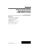

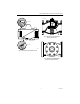
Table Of Contents

REPLACEMENT SEALS FOR V5055, V5097 GAS VALVES
60-0074—4 2
INSTALLATION
WARNING
Explosion Hazard.
Can cause serious injury, death or property
damage.
1. Only a trained, experienced service technician
should service the V5055/V5097 Gas Valve.
2. Before beginning installation, turn off the gas
supply and disconnect the power supply to the
valve actuator.
3. After installation, perform a complete checkout
including a gas leak check.
The bonnet and valve seals may be replaced without
removing the valve body from the gas line.
Use the following procedure to replace the seals in the
V5055/V5097 Gas Valve:
1.
Turn off the gas supply at the upstream manual
shutoff valve.
2.
Shut off all electrical power to the valve actuator.
3.
If a 7616BR Crank Arm Assembly is used with the
actuator, remove the crankarm assembly by pulling
the clip and loosening the clamp screw. Disengage
the arm from the actuator.
4.
Remove the actuator from the valve (loosen the
two set screws).
5.
Remove the valve bonnet (four bolts on the 3/4 to
1-1/2 in. valves, six bolts on the 2- to 3-in. valves,
and eight bolts on the 4-in. valves). Discard the old
rubber seals.
6.
Coat the new rubber seals with the grease
provided and position them as shown in Fig. 1 or 2.
WARNING
Explosion Hazard.
Can cause serious injury, death or property
damage.
Failure to properly position and seat the seals in
the valve body may result in a hazardous gas
leak.
7.
Carefully seat the bonnet assembly on the valve
body. Be sure the seals are in the proper positions.
On V5055/V5097 Gas Valves that have a spring
below the disk, be sure the spring is centered in
the indentation on the inside of the valve body.
NOTE: The 4-inch bonnet assembly may be replaced in
any position on the valve body.
8.
After positioning the bonnet assembly, replace the
screws removed in step 5 (see Fig. 3).
NOTE: When replacing the bonnet assembly on the
4-inch valve, be sure to draw it evenly into the
valve body. Finger tighten the eight screws.
Draw the bonnet assembly into the valve by
tightening, in order, screws 1,5,7, and 3 (two
turns each). See Fig. 3. Repeat until the bonnet
assembly is seated. Tighten the remaining
screws.
9.
Remount the actuator. Securely tighten the set
screws (50 to 60 inch-pounds).
10.
Replace the crank arm assembly if disconnected in
step 3.
11.
With the gas still off, cycle the actuator to check for
proper mechanical operation.