
Overview of Primary Product
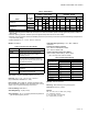
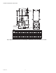


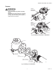


Table Of Contents

V5055A-F INDUSTRIAL GAS VALVES
11 60-2307—16
Scheduled Inspection and Maintenance
Setup and follow a schedule for periodic inspection and
maintenance, including the burner, all other controls, and the
valve(s) and actuator(s) for leaking oil. It is recommended that
the Valve Leak Test in the Checkout section be included in this
schedule. Refer to the Instructions for the primary safety
control for more information.
Valve Checkout for Oil Leakage from Actuator
1. Turn off the gas supply at the manual shutoff valve
located upstream from the valve(s) being serviced.
2. Shut off all electrical power to the valve actuator(s).
3. Mark and disconnect the wires from the actuator termi-
nals. Remove conduit and disengage the damper link-
age assembly (if applicable).
4. Loosen the two set screws from the valve to lift off the
actuator.
5. If the actuator is to be replaced and it did not leak
hydraulic fluid, skip to Step 11.
NOTE: It is good practice to inspect the inside of the
valve whenever the actuator is replaced. To do
so, remove the bonnet assembly, inspect the
valve and bonnet. If all is well, proceed to Step 7.
6. If the actuator leaked hydraulic fluid onto the valve (the
fluid is red), it must be cleaned off from the valve and
bonnet assembly.
a. Wipe off the outer valve body.
b. Remove the valve bonnet bolts and lift off the bonnet.
NOTE: V5055/V5097C and E Valves have additional
internal springs that will push the bonnet up as
the bolts are loosened.
c. Inspect the inside of the valve.
IMPORTANT
If fluid is present on the inside surfaces of the valve
body or bonnet surfaces, the bonnet assembly or
entire valve must be replaced. For part numbers, refer
to “Replacement Parts:” on page 4.
d. If the inside surfaces are clear of hydraulic fluid,
clean the bonnet assembly and be sure to remove all
hydraulic fluid from the inside and outside of the
actuator mounting curb. This is the “cup-like” area
around the valve stem. Avoid using a cleaning solu-
tion as it may damage the rubber seals used in the
valve.
7. If the valve bonnet assembly is in good condition and is
not replaced, replace the bonnet seal. Do not reuse the
old bonnet seal. See “Replacement Parts:” on page 4 for
the seal number.
8. Coat seals with grease provided and position in valve
body/bonnet assembly.
9. Carefully seat the bonnet assembly on the valve body.
Be sure the seals are in their proper position. On those
valves with a spring below the disc, be sure the spring is
centered in the indentation on the inside of the valve
body.
10. After positioning the bonnet assembly, replace the
screws removed earlier.
NOTE: When replacing the bonnet assembly on the 4”
valve, it must be drawn evenly into the valve
body. Finger tighten the 8 screws. Draw the
bonnet assembly into the valve by tightening, in
order, screws 1, 5, 7, 3 (two turns each).
Repeat until the assembly is seated. Tighten
the remaining screws.
11. Remount the actuator on the bonnet assembly. Tighten
the two set screws (50-60 inch pounds).
12. Replace the damper crank arm assembly.
13. Re-attach the wires removed from the actuator terminals
and turn on the electrical power.
14. With the gas still off, cycle the actuator to check for
proper mechanical operation.
CAUTION
Be sure to perform a bonnet seal and seat leak
check after installation.
Be sure to read and follow all instructions that come
with the actuators, valves, seal and bonnet kits.
Valve Bonnet Replacement
The entire valve bonnet may be replaced without removing the
valve body from the gas line. Do not disassemble the valve
bonnet assembly; the valve seat is not replaceable.
For part numbers, refer to Replacement Parts in the
Specifications section. Complete instructions for replacing the
bonnet assembly are included with the replacement part.
Replacement of Seals (Fig. 8 or 9)
When removing the bonnet to inspect and clean the valve,
install new seals (see Replacement Parts in Specifications
section). Coat the new seals with the grease provided, and
position them in the valve body as shown in Fig. 8 or 9.
Failure to properly position and seat the seals in the valve body
may result in a hazardous gas leak.
After the new bonnet assembly is installed, or the bonnet is
removed for any reason, check for gas leakage around the
bonnet seal. Turn on the gas at the manual valve. Paint the
seal area with a rich soap and water solution. Bubbles indicate
a gas leak. If a leak is detected, check to see that the bonnet
screws are tight. If necessary, turn off the gas again and
remove the bonnet to be sure the seals are properly seated.
Table 8. Gas Valve Replacement Seals.
Replacement Seal
Assy # Valve Size (in in.)
133393A 3/4, 1, 1-1/4, 1-1/2
133392A 2, 2-1/2, 3
137253A 4