
Datasheet


Sensing and Internet of Things 3
MICRO SWITCH Miniature Precision Limit Switches, 14CE Series
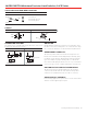
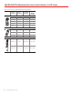
SWITCHING AND LEAD IDENTIFICATION
14CE
GREEN/YELLOW
GREY
1
BROWN
2
3
BLACK
SPDT
1 = Common
2 = Normally Closed
3 = Normally Open
PINOUTS
Connector - (dc) (Q) Connector (ac) (Q1)
1
3
2
1
3NO
NC
C
NO
NC
C
2
1
3
2
1
3NO
NC
C
NO
NC
C
2
CONNECTOR VERSIONS
The 14CE Series is available with a 4-pin, M12 size connector in
both bottom and side exit versions.
Q, Q2 Versions Q1 Version
8.0
15
OPTION Q
dc type 4 pin male
M12 thread
15
15
OPTION Q1
ac type, 4 pin male
,
1/2 in x 20 thread
MOUNTING
MICRO SWITCH 14CE Series switches are mounted by using
two M5 screws. The mounting holes are counter bored to keep
the screw heads within the overall switch housing dimensions.
GANG MOUNT CAPABILITY
The housing on the 14CE Series has been designed to ena-
ble the user to build his own multiple plunger switch by gang
mounting several switches. All pin plunger and roller plunger
types are suitable for gang mounting. There is a 16 mm dis-
tance between the plungers. Both Series are very versatile that
even a lever-type version could be added at the end of the row.
BOTTOM EXIT OR SIDE EXIT ORIENTATION
The CE Series has been designed with a pre-wired cable or
connector fitted in the bottom of the switch housing. Other
variations are available with a side-exit cable or connector.
GOLD CONTACT VERSIONS
For low energy applications, gold contact versions of the 14CE
switches can be supplied upon request.