Xenon™ 1900/1910 Xenon™ 1902/1912 Granit™ 1910i/1911i Area-Imaging Scanner User’s Guide
Disclaimer Honeywell International Inc. (“HII”) reserves the right to make changes in specifications and other information contained in this document without prior notice, and the reader should in all cases consult HII to determine whether any such changes have been made. The information in this publication does not represent a commitment on the part of HII.
Product Agency Compliance - Xenon 1900/1910 USA FCC Part 15 Subpart B Class B This device complies with part 15 of the FCC Rules. Operation is subject to the following two conditions: 1. This device may not cause harmful interference. 2. This device must accept any interference received, including interference that may cause undesired operation. This equipment has been tested and found to comply with the limits for a Class B digital device pursuant to part 15 of the FCC Rules.
Europe The CE marking indicates compliance to 2004/108/EC EMC Directive with Standards EN55022 CLASS B, EN55024, EN61000-3-2, EN61000-3-3 and 2011/65/EU RoHS directive. In addition, complies to 2006/95/EC Low Voltage Directive, when shipped with recommended power supply. European contact: Hand Held Products Europe B.V. Nijverheidsweg 9-13 5627 BT Eindhoven The Netherlands Honeywell International Inc. shall not be liable for use of our product with equipment (i.e., power supplies, personal computers, etc.
International LED Safety Statement LEDs have been tested and classified as “EXEMPT RISK GROUP” to the standard: IEC 62471:2006. CB Scheme Certified to CB Scheme IEC 60950-1, Second Edition. Laser Safety Statement If the following label is attached to your product, it indicates the product contains a laser engine or laser aimer: LASER LIGHT. Do Not Stare into Beam. Class 2 Laser Product. 1.0 mW Max output: 650nM IEC 60825-1 Ed 2 (2007). Pulse duration of 15.5mSec. Complies with 21 CFR 1040.10 and 1040.
Product Agency Compliance - Xenon 1902/1912 and CCB01-010BT Base USA FCC Part 15 Subpart C This device complies with part 15 of the FCC Rules. Operation is subject to the following two conditions: 1. This device may not cause harmful interference. 2. This device must accept any interference received, including interference that may cause undesired operation.
EN60950-1 Waste Electrical and Electronic Equipment Information Honeywell complies with Directive 2002/96/EC OF THE EUROPEAN PARLIAMENT AND OF THE COUNCIL on waste electrical and electronic equipment (WEEE). This product has required the extraction and use of natural resources for its production. It may contain hazardous substances that could impact health and the environment, if not properly disposed.
Korea This product meets Korean agency approval. Mexico Conforms to NOM-019. This product meets Cofetel approval. Russia Gost-R certificate.
Solids and Water Protection The Xenon 1902 has a rating of IP41, immunity of foreign particles and dripping water. Patents For patent information, please refer to www.hsmpats.com. Warning To reduce the possibility of heat-related injuries, avoid touching sections of the scanner that feel warm. ! Product Agency Compliance - Granit 1910i USA FCC Part 15 Subpart B Class B This device complies with part 15 of the FCC Rules. Operation is subject to the following two conditions: 1.
Conformité à la règlementation canadienne Cet appareil numérique de la Classe A est conforme à la norme NMB-003 du Canada. Son fonctionnement est assujetti aux conditions suivantes : 1. Cet appareil ne doit pas causer de brouillage préjudiciable. 2. Cet appareil doit pouvoir accepter tout brouillage reçu, y compris le brouillage pouvant causer un fonctionnement indésirable. TÜV-R Statement TÜV R listed: UL 60950-1, Second Edition and CSA C22.2 No.60950-1-07, Second Edition.
International LED Safety Statement LEDs have been tested and classified as “EXEMPT RISK GROUP” to the standard: IEC 62471:2006. CB Scheme Certified to CB Scheme IEC 60950-1, Second Edition. Laser Safety Statement If the following label is attached to your product, it indicates the product contains a laser engine or laser aimer: LASER LIGHT. DO NOT STARE INTO BEAM. CLASS 2 LASER PRODUCT. 1.0MW MAX OUTPUT: 650NM. IEC 60825-1 Ed 2 (2007). Complies with 21 CFR 1040.10 and 1040.
Product Agency Compliance - Granit 1911i and CCB02-100BT Base USA FCC Part 15 Subpart C This device complies with part 15 of the FCC Rules. Operation is subject to the following two conditions: 1. This device may not cause harmful interference. 2. This device must accept any interference received, including interference that may cause undesired operation.
EN60950-1 Waste Electrical and Electronic Equipment Information Honeywell complies with Directive 2002/96/EC OF THE EUROPEAN PARLIAMENT AND OF THE COUNCIL on waste electrical and electronic equipment (WEEE). This product has required the extraction and use of natural resources for its production. It may contain hazardous substances that could impact health and the environment, if not properly disposed.
Solids and Water Protection The Granit 1911i has a rating of IP65, immunity of foreign particles and dripping water. Patents For patent information, please refer to www.hsmpats.com. Warning To reduce the possibility of heat-related injuries, avoid touching sections of the scanner that feel warm.
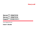
CCB01-010BT Base Part Number, Serial Number and Revision Information location Compliance Label locations
Granit 1910i/1911i Scanner Illumination output Laser Label location Part Number, Serial Number and Revision Information location Compliance label location
CCB02-100BT Base Compliance Label locations
Table of Contents Chapter 1 - Getting Started About This Manual ...............................................................................................................1-1 Unpacking Your Device .......................................................................................................1-1 Connecting the Device .........................................................................................................1-1 Connecting with USB .....................................................
RS232 Modifiers ................................................................................................................ 2-18 RS232 Baud Rate........................................................................................................ 2-18 RS232 Word Length: Data Bits, Stop Bits, and Parity ................................................. 2-19 RS232 Receiver Time-Out........................................................................................... 2-20 RS232 Handshaking.........
Scanner Modes ................................................................................................................... 3-9 Charge Only Mode......................................................................................................... 3-9 Linked Modes ................................................................................................................ 3-9 Unlinking the Scanner ....................................................................................................
Good Read and Error Indicators.......................................................................................... 4-2 Beeper – Good Read..................................................................................................... 4-2 Beeper Volume – Good Read........................................................................................ 4-2 Beeper Pitch – Good Read............................................................................................ 4-3 Vibrate – Good Read ....
Output Sequence Overview............................................................................................... 4-19 Output Sequence Editor .............................................................................................. 4-19 To Add an Output Sequence ....................................................................................... 4-19 Other Programming Selections.................................................................................... 4-20 Output Sequence Editor ....
Code 39 ............................................................................................................................... 7-4 Code 32 Pharmaceutical (PARAF) ................................................................................ 7-5 Full ASCII....................................................................................................................... 7-6 Code 39 Code Page ......................................................................................................
Postal Codes - 2D ............................................................................................................. 7-44 Single 2D Postal Codes:.............................................................................................. 7-44 Combination 2D Postal Codes:.................................................................................... 7-45 Postal Codes - Linear ........................................................................................................
Xenon 1900/1910 Corded Scanner Product Specifications .............................................. 12-1 Xenon 1902/1912 Cordless Scanner Product Specifications ............................................ 12-1 Granit 1910i Industrial Corded Scanner Product Specifications........................................ 12-2 Granit 1911i Industrial Cordless Scanner Product Specifications ..................................... 12-3 CCB01-010BT Charge Base Product Specifications........................................
ASCII Conversion Chart (Code Page 1252)........................................................................A-3 Lower ASCII Reference Table.............................................................................................A-4 ISO 2022/ISO 646 Character Replacements ......................................................................A-7 Unicode Key Maps ............................................................................................................
x
1 Getting Started About This Manual This User’s Guide provides installation and programming instructions for the Xenon™ 1900 and 1910 corded area-imaging scanners, the Xenon 1902 and 1912 cordless area-imaging scanners, and the Granit 1910i corded and 1911i cordless industrial scanners. Product specifications, dimensions, warranty, and customer support information are also included. Honeywell bar code scanners are factory programmed for the most common terminal and communications settings.
Corded Granit Scanner USB Connection: 2. If you are connecting a Granit scanner, make sure the cable is pushed tightly into the scanner. Loosen the locking plate and slide it over the base of the cable connector to lock the cable in place. Tighten the screw. CCB01-010BT Base USB Connection: CCB02-100BT Base USB Connection: Note: The power supply must be ordered separately, if needed.
3. If you are connecting a CCB01-010BT Base, make sure the cables are secured in the wireways in the bottom of the cordless base and the base sits flat on a horizontal surface. If you are connecting a CCB02-100BT Base, see Mounting a CCB02-100BT Base on page 1-8. 4. The scanner beeps. 5. Verify the scanner or cordless base operation by scanning a bar code from the Sample Symbols in the back of this manual. The unit defaults to a USB PC Keyboard. Refer to page 2-3 for other USB terminal settings.
CCB01-010BT Base Keyboard Wedge Connection: CCB02-100BT Base Keyboard Wedge Connection: Note: The power supply must be ordered separately, if needed. 4. If you are connecting a CCB01-010BT Base, make sure the cables are secured in the wireways in the bottom of the cordless base and the base sits flat on a horizontal surface. If you are connecting a CCB02-100BT Base, see Mounting a CCB02-100BT Base on page 1-8. 5. Turn the terminal/computer power back on. The scanner beeps. 6.
Connecting with RS232 Serial Port 1. Turn off power to the terminal/computer. 2. Connect the appropriate interface cable to the scanner. Note: For the scanner or cordless base to work properly, you must have the correct cable for your type of terminal/computer.
3. If you are connecting a Granit scanner, make sure the cable is pushed tightly into the scanner. Loosen the locking plate and slide it over the base of the cable connector to lock the cable in place. Tighten the screw. CCB01-010BT Base RS232 Serial Port Connection: CCB02-100BT Base RS232 Serial Port Connection: Note: The power supply must be ordered separately, if needed. 4.
Connecting with RS485 A Xenon scanner or cordless base can be connected for an IBM POS terminal interface. (This interface is not available in the Granit devices.) 1. Connect the appropriate interface cable to the device, then to the computer. Corded Xenon Scanner RS485 Connection: CCB01-010BT Base RS485 Connection: Note: The power supply must be ordered separately, if needed. 2.
Mounting a CCB01-010BT Charge Base 2.8 in. 72.1mm 3.35 in. 85.09mm 2.36 in. 59.84mm 8x32 thread x .39 in. (10mm) deep Mounting a CCB02-100BT Base The CCB02-100BT Base can be mounted on either a horizontal or vertical surface. The cables can be routed through either the top or the bottom of the base. The cables can be routed down through the bottom of the base, securing the cables in the wireways.
When mounted on a vertical surface, a locking system is used to secure the scanner when it is in the stand. When mounted on a horizontal surface, the locking mechanism should be set to unlocked (pushed up). When mounted on a vertical surface, the locking mechanism should be set to locked (pushed down). Locked position for vertical mount Unlocked position for horizontal mount Use 30mm screws, appropriate for the mounting surface material, to mount the base securely. 2.51 in. 63.7mm 5.31 in. 134.
Reading Techniques The Xenon 1900/1902 scanners have a view finder that projects a bright red aiming beam that corresponds to the scanner’s horizontal field of view. The Xenon 1910/1912 and Granit 1910i/1911i scanners have an aiming pattern . The aiming beam or pattern should be centered over the bar code, but it can be positioned in any direction for a good read.
Setting Custom Defaults You have the ability to create a set of menu commands as your own, custom defaults. To do so, scan the Set Custom Defaults bar code below before scanning the menu commands for your custom defaults. If a menu command requires scanning numeric codes from the back cover, then a Save code, that entire sequence will be saved to your custom defaults. When you have entered all the commands you want to save for your custom defaults, scan the Save Custom Defaults bar code.
1 - 12
2 Programming the Interface Introduction This chapter describes how to program your system for the desired interface. Programming the Interface - Plug and Play Plug and Play bar codes provide instant scanner set up for commonly used interfaces. Note: After you scan one of the codes, power cycle the host terminal to have the interface in effect. Keyboard Wedge If you want your system programmed for an IBM PC AT and compatibles keyboard wedge interface with a USA keyboard, scan the bar code below.
RS485 Scan one of the following “Plug and Play” codes to program the scanner for an IBM POS terminal interface. Note: This interface is not supported in Granit devices. After scanning one of these codes, you must power cycle the cash register.
RS485 Packet Length If you are using Packet mode, you can specify the size of the data “packet” that is sent to the host. Scan the Packet Length bar code, then then the packet size (from 20 - 256) from the Programming Chart inside the back cover of this manual, then Save. Default = 40. Packet Length USB IBM SurePos Scan one of the following “Plug and Play” codes to program the scanner for an IBM SurePos (USB handheld scanner) or IBM SurePos (USB tabletop scanner) interface.
USB HID Scan the following code to program the scanner for USB HID bar code scanners. USB HID Bar Code Scanner USB Serial Scan the following code to program the scanner to emulate a regular RS232-based COM Port. If you are using a Microsoft® Windows® PC, you will need to download a driver from the Honeywell website (www.honeywellaidc.com). The driver will use the next available COM Port number. Apple® Macintosh computers recognize the scanner as a USB CDC class device and automatically use a class driver.
ReM On Verifone® Ruby Terminal Default Settings Scan the following Plug and Play code to program the scanner for a Verifone Ruby terminal. This bar code sets the baud rate to 1200 bps and the data format to 8 data bits, no parity bit, 1 stop bit.
Datalogic™ Magellan® Aux Port Configuration Scan the following Plug and Play code to program the scanner for a Datalogic Magellan auxiliary port configuration. This bar code sets the baud rate to 9600 bps and the data format to 8 data bits, no parity, 1 stop bit. Datalogic Magellan Settings NCR Bioptic Aux Port Configuration Scan the following Plug and Play code to program the scanner for an NCR bioptic scanner auxiliary port configuration.
Wincor Nixdorf Beetle Settings Keyboard Country Layout Scan the appropriate country code below to program the keyboard layout for your country or language.
Keyboard Countries (Continued) Bulgaria (Cyrillic) Bulgaria (Latin) Canada (French legacy) Canada (French) Canada (Multilingual) Croatia Czech Czech (Programmers) Czech (QWERTY) Czech (QWERTZ) Denmark 2-8
Keyboard Countries (Continued) Dutch (Netherlands) Estonia Faroese Finland France Gaelic Germany Greek Greek (220 Latin) Greek (220) Greek (319 Latin) 2-9
Keyboard Countries (Continued) Greek (319) Greek (Latin) Greek (MS) Greek (Polytonic) Hebrew Hungarian (101 key) Hungary Iceland Irish Italian (142) Italy 2 - 10
Keyboard Countries (Continued) Japan ASCII Kazakh Kyrgyz (Cyrillic) Latin America Latvia Latvia (QWERTY) Lithuania Lithuania (IBM) Macedonia Malta Mongolian (Cyrillic) 2 - 11
Keyboard Countries (Continued) Norway Poland Polish (214) Polish (Programmers) Portugal Romania Russia Russian (MS) Russian (Typewriter) SCS Serbia (Cyrillic) 2 - 12
Keyboard Countries (Continued) Serbia (Latin) Slovakia Slovakia (QWERTY) Slovakia (QWERTZ) Slovenia Spain Spanish variation Sweden Switzerland (French) Switzerland (German) Tatar 2 - 13
Keyboard Countries (Continued) Turkey F Turkey Q Ukrainian United Kingdom United States (Dvorak) United States (Dvorak left) United Stated (Dvorak right) United States (International) Uzbek (Cyrillic) Keyboard Style This programs keyboard styles, such as Caps Lock and Shift Lock. If you have used Keyboard Conversion settings, they will override any of the following Keyboard Style settings. Default = Regular. Regular is used when you normally have the Caps Lock key off.
Caps Lock is used when you normally have the Caps Lock key on. Caps Lock Shift Lock is used when you normally have the Shift Lock key on (not common to U.S. keyboards). Shift Lock Automatic Caps Lock is used if you change the Caps Lock key on and off. The software tracks and reflects if you have Caps Lock on or off . This selection can only be used with systems that have an LED that notes the Caps Lock status (AT keyboards).
Convert All Characters to Upper Case Convert All Characters to Lower Case Control Character Output This selection sends a text string instead of a control character. For example, when the control character for a carriage return is expected, the output would display [CR] instead of the ASCII code of 0D. Refer to ASCII Conversion Chart (Code Page 1252) on page A-3. Only codes 00 through 1F are converted (the first column of the chart). Default = Off.
Windows Mode Prefix/Suffix Off Turbo Mode: The scanner sends characters to a terminal faster. If the terminal drops characters, do not use Turbo Mode. Default = Off. Turbo Mode On * Turbo Mode Off Numeric Keypad Mode: Sends numeric characters as if entered from a numeric keypad. Default = Off. Numeric Keypad Mode On * Numeric Keypad Mode Off Automatic Direct Connect Mode: This selection can be used if you have an IBM AT style terminal and the system is dropping characters. Default = Off.
RS232 Modifiers RS232 Baud Rate Baud Rate sends the data from the scanner to the terminal at the specified rate. The host terminal must be set for the same baud rate as the scanner. Default = 115,200.
RS232 Word Length: Data Bits, Stop Bits, and Parity Data Bits sets the word length at 7 or 8 bits of data per character. If an application requires only ASCII Hex characters 0 through 7F decimal (text, digits, and punctuation), select 7 data bits. For applications that require use of the full ASCII set, select 8 data bits per character. Default = 8. Stop Bits sets the stop bits at 1 or 2. Default = 1. Parity provides a means of checking character bit patterns for validity. Default = None.
RS232 Receiver Time-Out The unit stays awake to receive data until the RS232 Receiver Time-Out expires. A manual or serial trigger resets the timeout. When an RS232 receiver is sleeping, a character may be sent to wake up the receiver and reset the time-out. A transaction on the CTS line will also wake up the receiver. The receiver takes 300 milliseconds to completely come up.
XON/XOFF Standard ASCII control characters can be used to tell the scanner to start sending data (XON/XOFF On) or to stop sending data (XON/XOFF Off). When the host sends the XOFF character (DC3, hex 13) to the scanner, data transmission stops. To resume transmission, the host sends the XON character (DC1, hex 11). Data transmission continues where it left off when XOFF was sent. Default = XON/XOFF Off.
Scanner-Bioptic ACK/NAK Mode Bioptic ACK/NAK On must be scanned so the scanner will wait for an ACK or NAK from a bioptic scanner after each packet is sent. The Scanner-Bioptic ACK/NAK Timeout (below) controls how long the scanner will wait for a response. Default = Bioptic ACK/NAK Off. * Bioptic ACK/NAK Off Bioptic ACK/NAK On Scanner-Bioptic ACK/NAK Timeout This allows you to set the length (in milliseconds) for a timeout for a bioptic scanner’s ACK/NAK response.
3 Cordless System Operation Note: This chapter applies only to cordless scanning systems. It does not apply to corded scanners. How the Cordless Charge Base/Access Point Works A cordless charge base or an Access Point provide the link between the cordless scanner and the host system. The base/ Access Point contains an interface assembly and an RF communication module. The RF communication module performs the data exchange between the cordless scanner and the interface assembly.
Scan the linking bar code on the top of the Access Point to establish a connection between the Access Point and the scanner. The scanner emits a short beep and flashes the green LED to confirm a connection with the Access Point. The Access Point’s Page button remains blue.
Programming the Scanner and Base or Access Point When using the scanner and charge base or Access Point together as a system, menu parameters and configuration settings are stored in the charge base or Access Point. Therefore, when programming any menu configuration settings, the scanner must be linked to the intended charge base or Access Point. Note: This only applies when the scanner is linked to a charge base or Access Point.
About the Battery There is a danger of explosion if the batteries are incorrectly replaced. Replace the batteries with only the same or equivalent type recommended by the manufacturer. Dispose of used batteries according to the recycle program for batteries as directed by the governing agency for the country where the batteries are to be discarded. ! Power is supplied to the cordless scanner by a rechargeable battery that is integrated in the scanner handle.
Beeper and LED Sequences and Meaning The scanner contains LEDs on the rear of the unit that indicate linking status, decoding state, and battery condition. The base has LEDs on the top of the unit that indicate its power up, communication, and battery charge condition. The red LED = error; green LED = success of any type. Scanners and the CCB01-010BT base have audible indicators as well: 1 razz or error tone = error; 2 beeps = menu change; 1 beep = all other successes.
Base Power Communication Indicator Off Reset Scanner Scanning this bar code reboots the scanner and causes it to relink with the base or Access Point. Reset Scanner Scanning While in Base Cradle Note: This feature only applies to the CCB01-010BT base. If you want to be able to scan bar codes while the scanner is in the base cradle, scan the Scanning in Cradle On bar code below. If you want to only allow scanning when the scanner is out of the base cradle, scan Scanning in Cradle Off.
Default = External or Interface Cable Power. Base Charge Off External or Interface Cable Power External Power Only Paging Paging Mode By default, the paging button on the base or Access Point pages the scanners associated with that base or Access Point. If you want the paging button on your base or Access Point to be disabled, scan the Paging Mode Off bar code, below. When Paging Mode is off, the base or Access Point will no longer page scanners when the button is pressed.
High (4200 Hz) Error Indicators Beeper Pitch - Base Error Note: This feature only applies to the CCB01-010BT base. The CCB01-010BT base can be configured to beep at a particular pitch when an error occurs, such as transmission problems to a host system. The beeper pitch codes modify the pitch (frequency) of the error tone the base emits when there is an error. Default = Low.
Scanner Address Scan the bar code below to determine the address of the scanner you are using. Scanner Address Base or Access Point Address Scan the bar code below to determine the address of the base or Access Point you are using. Base Address Scanner Modes Your scanner is capable of working in single scanner mode, multiple scanner mode, or with Bluetooth devices other than the charge base or Access Point.
Locked Link Mode - Single Scanner If you link a scanner to a base or an Access Point using the Locked Link Mode, other scanners are blocked from being linked if they are inadvertently placed into the base, or if the Access Point linking bar code is scanned. If you do place a different scanner into a base, it will charge the scanner, but the scanner will not be linked.
options for the scanner or the base and to set the alarm duration, scan the appropriate bar code below and then set the time-out duration (from 0-3000 seconds) by scanning digits on the Programming Chart inside the back cover, then scanning Save. Default = 0 sec (no alarm). Base Alarm Duration Note: The Access Point does not have a base alarm. Scanner Alarm Duration Note: If you are out of range when you scan a bar code, you will receive an error tone even if you do not have the alarm set.
When there is no activity within a specified time period, the scanner enters low power mode. Scan the appropriate scanner power time-out bar code to change the time-out duration (in seconds). Note: Scanning zero (0) is the equivalent of setting no time-out. If there are no trigger pulls during the timer interval, the scanner goes into power down mode. Whenever the trigger is enabled, the timer is reset.
Scan one of the bar codes below to set the scanner’s power output to Full Power (100%), Medium Power (35%), Medium Low Power (5%), or Low Power (1%). Default = Full Power. Note: Setting a Granit scanner to anything lower than Full Power changes it to Class II Bluetooth. * Full Power Medium Power Medium Low Power Low Power Batch Mode Batch mode is used to store bar code data when a scanner is out of range of its base or Access Point, or when performing inventory.
Inventory Batch Mode Persistent Batch Mode Batch Mode Beep When scanning in Inventory Batch Mode (page 3-14), the scanner beeps every time a bar code is scanned. If using a Granit scanner, it also vibrates. When Batch Mode Beep is On, you will also hear a click when each bar code is sent to the host. If you do not want to hear these clicks, scan Batch Mode Beep Off. Default = Batch Mode Beep On.
Batch Mode Quantity When in Batch Mode, you may wish to transmit the number of multiple bar codes scanned, rather than a single bar code multiple times. For example, if you scan three bar codes called XYZ with Batch Mode Quantity Off, when you transmit your data it will appear as XYZ three times. Using Batch Mode Quantity On and the Quantity Codes (page 3-16), you could output your data as “XYZ, 00003” instead.
1 2 3 4 5 6 7 8 9 Batch Mode Output Order When batch data is transmitted, select whether you want that data sent as FIFO (first-in first-out), or LIFO (last-in first-out). Default = Batch Mode FIFO.
Total Records If you wish to output the total number of bar codes scanned when in Batch Mode, scan Total Records. Total Records Delete Last Code If you want to delete the last bar code scanned when in Batch Mode, scan Delete Last Code. Delete Last Code Clear All Codes If you want to clear the scanner’s buffer of all data accumulated in Batch Mode, scan Clear All Codes.
Batch Mode Transmit Delay Medium (500 ms) Batch Mode Transmit Delay Long (1000 ms) Multiple Scanner Operation Note: Multiple Scanner Operation Mode allows you to link up to 7 scanners to one base or Access Point. You cannot join an 8th scanner until you unlink one of the 7 scanners or take a scanner out of range. To put the scanner in multiple scanner mode, scan the bar code below.
0004 0005 0006 0007 Reset You may also scan the Scanner Name bar code below and scan a number for the scanner name. For example, if you wanted to name the linked scanner “312,” you would scan the bar code below, scan the 3, 1, and 2 bar codes on the Programming Chart inside the back cover of this manual, then scan Save. Scan the Reset bar code and wait for the scanner to relink to the base.
Application Work Group Selection This programming selection allows you to assign a scanner to a work group by scanning the bar code below. You may then program the settings (e.g., beeper volume, prefix/suffix, data formatter) that your application requires. Default = Group 0. * Group 0 Group 1 Group 2 Group 3 Group 4 Group 5 Group 6 Resetting the Factory Defaults: All Application Work Groups The following bar code defaults all of the work groups to the factory default settings.
Resetting the Custom Defaults: All Application Work Groups If you want the custom default settings restored to all of the work groups, scan the Custom Product Default Settings bar code below. (If there are no custom defaults, it will reset the work groups to the factory defaults.) See "Setting Custom Defaults" on page 1-11 for further information about custom defaults.
2 3 4 5 6 7 8 9 Save Virtual Keyboard Once your scanner has been connected directly to an iPad, smart phone, or laptop, you can toggle the virtual keyboard on your device with a quick double pull of the scanner trigger. Note: This feature is not supported in Granit devices.
Bluetooth HID Keyboard Disconnect If your scanner has been connected directly to an iPad, smart phone, or laptop using Bluetooth HID Keyboard Connect (page 3-21), you must disconnect it in order to once again communicate with the base or Access Point. Scan the Bluetooth HID Keyboard Disconnect bar code to unlink the scanner from the currently linked host. Scan the linking bar code on the base or Access Point to relink the scanner.
Auto Reconnect Mode Auto Reconnect controls whether or not the scanner automatically begins the relink process when a loss of connection is detected. When the Auto Reconnect On bar code is scanned, the scanner begins the relink process immediately, without user intervention. Default = Auto Reconnect On. * Auto Reconnect On Auto Reconnect Off Note: If you are connecting to a Bluetooth Interface Module, set Auto Reconnect to Off.
Scan the Maximum Link Attempts bar code, then scan the number of attempts for the setting (from 0-100) from the inside back cover. Scan Save to save the setting. Default = 0. Maximum Link Attempts Note: When Auto Reconnect Mode is On, setting Maximum Link Attempts to zero will cause the scanner to try to link until the Power Time-Out Timer setting (see page 3-11) expires.
Host Acknowledgment Some applications require that the host terminal (or server) validate incoming bar code data (database look-up) and provide acknowledgement to the scanner whether or not to proceed. In Host ACK Mode, the scanner waits for this acknowledgement after each scan. Visual and audible acknowledgements provide valuable feedback to the scan operator.
Host ACK On/Off Host ACK On * Host ACK Off Host ACK Responses Command Action [ESC] a, Double beeps to indicate a successful menu change was made. [ESC] b, Razz or error tone to indicate a menu change was unsuccessful. [ESC] 1, The green LED illuminates for 135 milliseconds followed by a pause. [ESC] 2, The green LED illuminates for 2 seconds followed by a pause. [ESC] 3, The green LED illuminates for 5 seconds followed by a pause. [ESC] 4, Emits a beep at a low pitch.
3 - 28
4 Input/Output Settings Power Up Beeper Note: This feature does not apply to the CCB02-100BT base. The scanner can be programmed to beep when it’s powered up. If you are using a cordless system, the base can also be programmed to beep when it is powered up. Scan the Off bar code(s) if you don’t want a power up beep. Default = Power Up Beeper On - Scanner.
Trigger Click To hear an audible click every time the scanner trigger is pressed, scan the Trigger Click On bar code below. Scan the Trigger Click Off code if you don’t wish to hear the click. (This feature has no effect on serial or automatic triggering.) Default = Trigger Click Off. *Trigger Click Off Trigger Click On Good Read and Error Indicators Beeper – Good Read The beeper may be programmed On or Off in response to a good read.
Beeper Pitch – Good Read The beeper pitch codes modify the pitch (frequency) of the beep the scanner emits on a good read. The Medium pitch differs for the Xenon and Granit scanners. Default = Medium. Low (1600 Hz) * Medium - Xenon (2700 Hz) * Medium - Granit (3200 Hz) High (4200 Hz) Vibrate – Good Read Note: Vibration settings apply only to Granit Devices. The scanner vibrates once when a bar code is successfully read, and twice when a programming bar code is successfully read.
Beeper Pitch – Error The beeper pitch codes modify the pitch (frequency) of the sound the scanner emits when there is a bad read or error. Default = Razz. * Razz (250 Hz) Medium (3250 Hz) High (4200 Hz) Beeper Duration – Good Read The beeper duration codes modify the length of the beep the scanner emits on a good read. Default = Normal. * Normal Beep Short Beep LED – Good Read The LED indicator can be programmed On or Off in response to a good read. Default = On.
Number of Beeps – Good Read The number of beeps of a good read can be programmed from 1 - 9. The same number of beeps will be applied to the beeper and LED in response to a good read. For example, if you program this option to have five beeps, there will be five beeps and five LED flashes in response to a good read. The beeps and LED flashes are in sync with one another.
Long Delay (1,500 ms) User-Specified Good Read Delay If you want to set your own length for the good read delay, scan the bar code below, then set the delay (from 0 - 30,000 milliseconds) by scanning digits from the inside back cover, then scanning Save. User-Specified Good Read Delay Manual Trigger Modes When in manual trigger mode, the scanner scans until a bar code is read, or until the trigger is released. Two modes are available, Normal and Enhanced.
* High Serial Trigger Mode You can activate the scanner either by pressing the trigger, or using a serial trigger command (see Trigger Commands on page 11-3). When in serial mode, the scanner scans until a bar code has been read or until the deactivate command is sent. The scanner can also be set to turn itself off after a specified time has elapsed (see Read Time-Out, which follows).
LED Illumination - Presentation Mode If you wish to set the illumination LED brightness, scan one of the bar codes below. This sets the LED illumination for the scanner when it is in Presentation Mode. (If the scanner is triggered manually, the LED illumination will switch to the setting for a manual trigger. See "LED Illumination - Manual Trigger" on page 4-6.) Default = High. Note: The LEDs are like a flash on a camera.
If a bar code is not touched by a predefined window, it will not be decoded or output by the scanner. If Presentation Centering is turned on by scanning Presentation Centering On, the scanner only reads codes that pass through the centering window you specify using the Top of Presentation Centering Window, Bottom of Presentation Centering Window, Left, and Right of Presentation Centering Window bar codes. In the example below, the white box is the centering window.
Bottom of Presentation Centering Window Left of Presentation Centering Window Right of Presentation Centering Window In-Stand Sensor Mode Note: The In-Stand Sensor feature only applies to Xenon products. This feature senses when the scanner is removed from the stand and tells it to begin manual triggering. When Sensor On is enabled, the scanner defaults to Streaming Presentation Mode when it is in the stand, and to Manual Trigger Mode when it is removed from the stand. Default = Sensor On.
CodeGate On Out-of-Stand Streaming Presentation™ Mode When in Streaming Presentation mode, the scanner’s aimer goes out after a short time, but the scan illumination remains on all the time to continuously search for bar codes. Two modes are available, Normal and Enhanced. Normal mode offers good scan speed and the longest working ranges (depth of field). Enhanced mode will give you the highest possible scan speed but slightly less range than Normal mode.
Hands Free Time-Out The Scan Stand and Presentation Modes are referred to as “hands free” modes. If the scanner’s trigger is pulled when using a hands free mode, the scanner changes to manual trigger mode. You can set the time the scanner should remain in manual trigger mode by setting the Hands Free Time-Out. Once the time-out value is reached, (if there have been no further trigger pulls) the scanner reverts to the original hands free mode.
2D Reread Delay Sometimes 2D bar codes can take longer to read than other bar codes. If you wish to set a separate Reread Delay for 2D bar codes, scan one of the programming codes that follows. 2D Reread Delay Off indicates that the time set for Reread Delay is used for both 1D and 2D bar codes. Default = 2D Reread Delay Off.
Activation Character This sets the character used to trigger scanning when using Character Activation Mode. On the ASCII Conversion Chart (Code Page 1252), page A-3, find the hex value that represents the character you want to use to trigger scanning. Scan the following bar code, then use the Programming Chart to read the alphanumeric combination that represents that ASCII character. Scan Save to finish. Default = 12 [DC2].
On Deactivation Character This sets the character used to terminate scanning when using Character Deactivation Mode. On the ASCII Conversion Chart (Code Page 1252), page A-3, find the hex value that represents the character you want to use to terminate scanning. Scan the following bar code, then use the Programming Chart inside the back cover of this manual to read the alphanumeric combination that represents that ASCII character. Scan Save to finish. Default = 14 [DC4].
User-Specified Aimer Delay If you want to set your own length for the duration of the delay, scan the bar code below, then set the time-out by scanning digits (0 - 4,000 ms) from the Programming Chart inside the back cover of this manual, then scan Save. Delay Duration Aimer Mode This feature allows you to turn the aimer on and off. When the Interlaced bar code is scanned, the aimer is interlaced with the illumination LEDs. Default = Interlaced.
In the example below, the white box is the centering window. The centering window has been set to 20% left, 30% right, 8% top, and 25% bottom. Since Bar Code 1 passes through the centering window, it will be read. Bar Code 2 does not pass through the centering window, so it will not be read. 0% Bar Code 1 10 Bar Code 2 20 30 40 50 60 70 80 90 100 0 10 20 30 40 50 60 70 80 90 100% Note: A bar code needs only to be touched by the centering window in order to be read.
Right of Centering Window Preferred Symbology The scanner can be programmed to specify one symbology as a higher priority over other symbologies in situations where both bar code symbologies appear on the same label, but the lower priority symbology cannot be disabled. For example, you may be using the scanner in a retail setting to read U.P.C. symbols, but have occasional need to read a code on a drivers license.
If you want to set additional low priority symbologies, scan FF, then scan the 2 digit hex value from the Programming Chart for the next symbology. You can program up to 5 low priority symbologies. Scan Save to save your selection. Default = None. Low Priority Symbology Preferred Symbology Time-out Once you have enabled Preferred Symbology and entered the high and low priority symbologies, you must set the time-out period.
5. End Output Sequence Editor Scan F F to enter an Output Sequence for an additional symbology, or Save to save your entries. Other Programming Selections • Discard This exits without saving any Output Sequence changes. Output Sequence Example In this example, you are scanning Code 93, Code 128, and Code 39 bar codes, but you want the scanner to output Code 39 1st, Code 128 2nd, and Code 93 3rd, as shown below. Note: Code 93 must be enabled to use this example.
41 start character match for Code 39, 41h = “A” FF termination string for first code 6A code identifier for Code 128 0013 B - Code 128 sample length (12) plus CR suffix (1) = 13 42 start character match for Code 128, 42h = “B” FF termination string for second code 69 code identifier for Code 93 0012 C - Code 93 sample length (11) plus CR suffix (1) = 12 43 start character match for Code 93, 43h = “C” FF termination string for third code Output Sequence Editor Enter Sequence Default Seq
When the output sequence is Off, the bar code data is output to the host as the scanner decodes it. Default = Off. Note: This selection is unavailable when the Multiple Symbols Selection is turned on. Required On/Not Required *Off Multiple Symbols When this programming selection is turned On, it allows you to read multiple symbols with a single pull of the scanner’s trigger.
Video Reverse Video Reverse is used to allow the scanner to read bar codes that are inverted. The Video Reverse Off bar code below is an example of this type of bar code. Scan Video Reverse Only to read only inverted bar codes. Scan Video Reverse and Standard Bar Codes to read both types of codes. Note: After scanning Video Reverse Only, menu bar codes cannot be read. You must scan Video Reverse Off or Video Reverse and Standard Bar Codes in order to read menu bar codes.
* Upright Vertical, Bottom to Top Upside Down Vertical, Top to Bottom 4 - 24
5 Data Editing Prefix/Suffix Overview When a bar code is scanned, additional information is sent to the host computer along with the bar code data. This group of bar code data and additional, user-defined data is called a “message string.” The selections in this section are used to build the user-defined data into the message string. Prefix and Suffix characters are data characters that can be sent before and after scanned data.
Example: Add a Tab Suffix to All Symbologies Step 1. Scan Add Suffix. Step 2. Scan 9, 9 from the Programming Chart inside the back cover of this manual to apply this suffix to all symbologies. Step 3. Scan 0, 9 from the Programming Chart inside the back cover of this manual. This corresponds with the hex value for a horizontal tab, shown in the ASCII Conversion Chart (Code Page 1252), beginning on page A-3. Scan Save, or scan Discard to exit without saving.
Clear One Suffix Clear All Suffixes Function Code Transmit When this selection is enabled and function codes are contained within the scanned data, the scanner transmits the function code to the terminal. Charts of these function codes are provided in Supported Interface Keys starting on page 9-3. When the scanner is in keyboard wedge mode, the scan code is converted to a key code before it is transmitted. Default = Enable.
Next, scan the Character to Trigger Delay bar code, then the 2-digit hex value for the ASCII character that will trigger the delay ASCII Conversion Chart (Code Page 1252), beginning on page A-3. Delay Length Character to Trigger Delay To remove this delay, scan the Delay Length bar code, and set the number of delays to 0. Scan the Save bar code using the Programming Chart inside the back cover of this manual.
6 Data Formatting Data Format Editor Introduction You may use the Data Format Editor to change the scanner’s output. For example, you can use the Data Format Editor to insert characters at certain points in bar code data as it is scanned. The selections in the following pages are used only if you wish to alter the output. Default Data Format setting = None. Normally, when you scan a bar code, it is output automatically.
Step 5. Length Specify what length (up to 9999 characters) of data will be acceptable for this symbology. Scan the four digit data length from the Programming Chart inside the back cover of this manual. For example, 50 characters is entered as 0050. Note: 9999 indicates all lengths. Step 6. Editor Commands Refer to Data Format Editor Commands (page 6-3). Scan the symbols that represent the command you want to enter. Step 7. Scan Save to save your data format, or Discard to exit without saving your changes.
Terminal ID Table Terminal USB Serial Keyboard Model(s) PC keyboard (HID) Mac Keyboard PC Keyboard (Japanese) Serial (COM driver required) HID POS USB SurePOS Handheld USB SurePOS Tabletop RS232 TTL RS232 True RS485 (IBM-HHBCR 1+2, 46xx) PS2 compatibles AT compatibles Terminal ID 124 125 134 130 131 128 129 000 000 051 003 002 Data Format Editor Commands When working with the Data Format Editor, a virtual cursor is moved along your input data string.
F1 is the “Send all characters” command 0D is the hex value for a CR The data is output as: 1234567890 ABCDEFGHIJ Send all characters up to a particular character F3 Include in the output message all characters from the input message, starting with the character at the current cursor position and continuing to, but not including, the search character “ss,” followed by an insert character. The cursor is moved forward to the “ss” character.
Insert a character multiple times F4 Send “xx” character “nn” times in the output message, leaving the cursor in the current position. Syntax = F4xxnn where xx stands for the insert character’s hex value for its ASCII code, and nn is the numeric value (00-99) for the number of times it should be sent. Refer to the ASCII Conversion Chart (Code Page 1252), beginning on page A-3 for decimal, hex and character codes.
Insert bar code length B4 Insert the bar code’s length in the output message, without moving the cursor. The length is expressed as a numeric string and does not include leading zeroes. B3 and B4 Example: Insert the symbology name and length Send the symbology name and length before the bar code data from the bar code above. Break up these insertions with spaces. End with a carriage return.
F5 Example: Move the cursor forward and send the data Move the cursor forward 3 characters, then send the rest of the bar code data from the bar code above. End with a carriage return.
F8 Example: Send bar code data that starts after a particular character Search for the letter “D” in bar codes and send all the data that follows, including the “D.
Search forward for a non-matching character E6 Search the input message forward for the first non-“xx” character from the current cursor position, leaving the cursor pointing to the non-“xx” character. Syntax = E6xx where xx stands for the search character’s hex value for its ASCII code. Refer to the ASCII Conversion Chart (Code Page 1252), beginning on page A-3 for decimal, hex and character codes.
Stop suppressing characters FC Disables suppress filter and clear all suppressed characters. Syntax = FC. Replace characters E4 Replaces up to 15 characters in the output message, without moving the cursor. Replacement continues until the E5 command is encountered. Syntax = E4nnxx1xx2yy1yy2...
If this bar code is read, the next data format, if there is one, will be used on the data. If there is no other format, the format fails and the raw data is output as AB1234. If this bar code is read: the data is output as: 1234AB Check for non-numeric character ED Check to make sure there is a non-numeric ASCII character at the current cursor position. The format is aborted if the character is numeric.
Data Formatter When Data Formatter is turned Off, the bar code data is output to the host as read, including prefixes and suffixes. Data Formatter Off You may wish to require the data to conform to a data format you have created and saved. The following settings can be applied to your data format: Data Formatter On, Not Required, Keep Prefix/Suffix Scanned data is modified according to your data format, and prefixes and suffixes are transmitted.
Data Format Non-Match Error Tone When a bar code is encountered that doesn’t match your required data format, the scanner normally generates an error tone. However, you may want to continue scanning bar codes without hearing the error tone. If you scan the Data Format Non-Match Error Tone Off bar code, data that doesn’t conform to your data format is not transmitted, and no error tone will sound.
For example, you may have set your device to the data format you saved as Data Format 3. You can switch to Data Format 1 for a single trigger pull by scanning the Single Scan-Data Format 1 bar code below. The next bar code that is scanned uses Data Format 1, then reverts back to Data Format 3.
7 Symbologies This programming section contains the following menu selections. Refer to Chapter 11 for settings and defaults.
EXAMPLE: Decode only those bar codes with a count of 15 characters. Min. length = 15Max. length = 15 For a value other than the minimum and maximum message length defaults, scan the bar codes included in the explanation of the symbology, then scan the digit value of the message length and Save bar codes on the Programming Chart inside the back cover of this manual. The minimum and maximum lengths and the defaults are included with the respective symbologies.
Validate Modulo 16, but Don’t Transmit Validate Modulo 16 and Transmit Codabar Concatenation Codabar supports symbol concatenation. When you enable concatenation, the scanner looks for a Codabar symbol having a “D” start character, adjacent to a symbol having a “D” stop character. In this case the two messages are concatenated into one with the “D” characters omitted. A 1 2 3 4 D D 5 6 7 8 A Select Require to prevent the scanner from decoding a single “D” Codabar symbol without its companion.
Code 39 < Default All Code 39 Settings > Code 39 On/Off * On Off Code 39 Start/Stop Characters Start/Stop characters identify the leading and trailing ends of the bar code. You may either transmit, or not transmit Start/ Stop characters. Default = Don’t Transmit. Transmit * Don’t Transmit Code 39 Check Character No Check Character indicates that the scanner reads and transmits bar code data with or without a check character.
Code 39 Message Length Scan the bar codes below to change the message length. Refer to Message Length Description (page 7-1) for additional information. Minimum and Maximum lengths = 0-48. Minimum Default = 0, Maximum Default = 48. Minimum Message Length Maximum Message Length Code 39 Append This function allows the scanner to append the data from several Code 39 bar codes together before transmitting them to the host computer.
Full ASCII If Full ASCII Code 39 decoding is enabled, certain character pairs within the bar code symbol will be interpreted as a single character. For example: $V will be decoded as the ASCII character SYN, and /C will be decoded as the ASCII character #. Default = Off.
Interleaved 2 of 5 < Default All Interleaved 2 of 5 Settings > Interleaved 2 of 5 On/Off * On Off Check Digit No Check Digit indicates that the scanner reads and transmits bar code data with or without a check digit. When Check Digit is set to Validate, but Don’t Transmit, the unit only reads Interleaved 2 of 5 bar codes printed with a check digit, but will not transmit the check digit with the scanned data.
Maximum Message Length NEC 2 of 5 < Default All NEC 2 of 5 Settings > NEC 2 of 5 On/Off * On Off Check Digit No Check Digit indicates that the scanner reads and transmits bar code data with or without a check digit. When Check Digit is set to Validate, but Don’t Transmit, the unit only reads NEC 2 of 5 bar codes printed with a check digit, but will not transmit the check digit with the scanned data.
NEC 2 of 5 Message Length Scan the bar codes below to change the message length. Refer to Message Length Description (page 7-1) for additional information. Minimum and Maximum lengths = 2-80. Minimum Default = 4, Maximum Default = 80. Minimum Message Length Maximum Message Length Code 93 < Default All Code 93 Settings > Code 93 On/Off * On Off Code 93 Message Length Scan the bar codes below to change the message length. Refer to Message Length Description (page 7-1) for additional information.
Code 93 Append This function allows the scanner to append the data from several Code 93 bar codes together before transmitting them to the host computer. When this function is enabled, the scanner stores those Code 93 bar codes that start with a space (excluding the start and stop symbols), and does not immediately transmit the data. The scanner stores the data in the order in which the bar codes are read, deleting the first space from each.
Straight 2 of 5 Industrial (three-bar start/stop) Straight 2 of 5 Industrial On/Off On * Off Straight 2 of 5 Industrial Message Length Scan the bar codes below to change the message length. Refer to Message Length Description (page 7-1) for additional information. Minimum and Maximum lengths = 1-48. Minimum Default = 4, Maximum Default = 48.
Straight 2 of 5 IATA (two-bar start/stop) Straight 2 of 5 IATA On/Off On * Off Straight 2 of 5 IATA Message Length Scan the bar codes below to change the message length. Refer to Message Length Description (page 7-1) for additional information. Minimum and Maximum lengths = 1-48. Minimum Default = 4, Maximum Default = 48.
Matrix 2 of 5 Matrix 2 of 5 On/Off On * Off Matrix 2 of 5 Message Length Scan the bar codes below to change the message length. Refer to Message Length Description (page 7-1) for additional information. Minimum and Maximum lengths = 1-80. Minimum Default = 4, Maximum Default = 80.
Code 11 Code 11 On/Off On * Off Check Digits Required This option sets whether 1 or 2 check digits are required with Code 11 bar codes. Default = Two Check Digits. One Check Digit * Two Check Digits Code 11 Message Length Scan the bar codes below to change the message length. Refer to Message Length Description (page 7-1) for additional information. Minimum and Maximum lengths = 1-80. Minimum Default = 4, Maximum Default = 80.
Code 128 Code 128 On/Off * On Off ISBT 128 Concatenation In 1994 the International Society of Blood Transfusion (ISBT) ratified a standard for communicating critical blood information in a uniform manner. The use of ISBT formats requires a paid license.
Code 128 Append This function allows the scanner to append the data from several Code 128 bar codes together before transmitting them to the host computer. When the scanner encounters a Code 128 bar code with the append trigger character(s), it buffers Code 128 bar codes until it reads a Code 128 bar code that does not have the append trigger. The data is then transmitted in the order in which the bar codes were read (FIFO). Default = On.
GS1-128 GS1-128 On/Off * On Off GS1-128 Message Length Scan the bar codes below to change the message length. Refer to Message Length Description (page 7-1) for additional information. Minimum and Maximum lengths = 1-80. Minimum Default = 1, Maximum Default = 80.
Telepen Telepen On/Off On * Off Telepen Output Using AIM Telepen Output, the scanner reads symbols with start/stop pattern 1 and decodes them as standard full ASCII (start/stop pattern 1). When Original Telepen Output is selected, the scanner reads symbols with start/stop pattern 1 and decodes them as compressed numeric with optional full ASCII (start/stop pattern 2). Default = AIM Telepen Output.
UPC-A UPC-A On/Off * On Off Note: To convert UPC-A bar codes to EAN-13, see Convert UPC-A to EAN-13 on page 7-24. UPC-A Check Digit This selection allows you to specify whether the check digit should be transmitted at the end of the scanned data or not. Default = On. * On Off UPC-A Number System The numeric system digit of a U.P.C. symbol is normally transmitted at the beginning of the scanned data, but the unit can be programmed so it will not transmit it. Default = On.
UPC-A Addenda This selection adds 2 or 5 digits to the end of all scanned UPC-A data. Default = Off for both 2 Digit and 5 Digit Addenda. 2 Digit Addenda On * 2 Digit Addenda Off 5 Digit Addenda On * 5 Digit Addenda Off UPC-A Addenda Required When Required is scanned, the scanner will only read UPC-A bar codes that have addenda. You must then turn on a 2 or 5 digit addenda listed on page 7-20. Default = Not Required.
UPC-A/EAN-13 with Extended Coupon Code Use the following codes to enable or disable UPC-A and EAN-13 with Extended Coupon Code. When left on the default setting (Off), the scanner treats Coupon Codes and Extended Coupon Codes as single bar codes. If you scan the Allow Concatenation code, when the scanner sees the coupon code and the extended coupon code in a single scan, it transmits both as separate symbologies. Otherwise, it transmits the first coupon code it reads.
UPC-E0 UPC-E0 On/Off Most U.P.C. bar codes lead with the 0 number system. To read these codes, use the UPC-E0 On selection. If you need to read codes that lead with the 1 number system, use UPC-E1 (page 7-24). Default = On. * UPC-E0 On UPC-E0 Off UPC-E0 Expand UPC-E Expand expands the UPC-E code to the 12 digit, UPC-A format. Default = Off. On * Off UPC-E0 Addenda Required When Required is scanned, the scanner will only read UPC-E bar codes that have addenda.
UPC-E0 Addenda Separator When this feature is On, there is a space between the data from the bar code and the data from the addenda. When turned Off, there is no space. Default = On. * On Off UPC-E0 Check Digit Check Digit specifies whether the check digit should be transmitted at the end of the scanned data or not. Default = On. * On Off UPC-E0 Leading Zero This feature allows the transmission of a leading zero (0) at the beginning of scanned data. To prevent transmission, scan Off. Default = On.
5 Digit Addenda On * 5 Digit Addenda Off UPC-E1 Most U.P.C. bar codes lead with the 0 number system. For these codes, use UPC-E0 (page 7-22). If you need to read codes that lead with the 1 number system, use the UPC-E1 On selection. Default = Off. UPC-E1 On * UPC-E1 Off EAN/JAN-13 EAN/JAN-13 On/Off * On Off Convert UPC-A to EAN-13 When UPC-A Converted to EAN-13 is selected, UPC-A bar codes are converted to 13 digit EAN-13 codes by adding a zero to the front.
* Do not Convert UPC-A EAN/JAN-13 Check Digit This selection allows you to specify whether the check digit should be transmitted at the end of the scanned data or not. Default = On. * On Off EAN/JAN-13 Addenda This selection adds 2 or 5 digits to the end of all scanned EAN/JAN-13 data. Default = Off for both 2 Digit and 5 Digit Addenda.
* Not Required EAN/JAN-13 Addenda Separator When this feature is On, there is a space between the data from the bar code and the data from the addenda. When turned Off, there is no space. Default = On. * On Off Note: If you want to enable or disable EAN13 with Extended Coupon Code, refer to UPC-A/EAN-13 with Extended Coupon Code (page 7-21). ISBN Translate When On is scanned, EAN-13 Bookland symbols are translated into their equivalent ISBN number format. Default = Off.
EAN/JAN-8 EAN/JAN-8 On/Off * On Off EAN/JAN-8 Check Digit This selection allows you to specify whether the check digit should be transmitted at the end of the scanned data or not. Default = On. * On Off EAN/JAN-8 Addenda This selection adds 2 or 5 digits to the end of all scanned EAN/JAN-8 data. Default = Off for both 2 Digit and 5 Digit Addenda.
* 5 Digit Addenda Off EAN/JAN-8 Addenda Required When Required is scanned, the scanner will only read EAN/JAN-8 bar codes that have addenda. Default = Not Required. Required * Not Required EAN/JAN-8 Addenda Separator When this feature is On, there is a space between the data from the bar code and the data from the addenda. When turned Off, there is no space. Default = On.
MSI MSI On/Off On * Off MSI Check Character Different types of check characters are used with MSI bar codes. You can program the scanner to read MSI bar codes with Type 10 check characters. Default = Validate Type 10, but Don’t Transmit. When Check Character is set to Validate Type 10/11 and Transmit, the scanner will only read MSI bar codes printed with the specified type check character(s), and will transmit the character(s) at the end of the scanned data.
Validate Type 11 then Type 10 Character and Transmit Disable MSI Check Characters MSI Message Length Scan the bar codes below to change the message length. Refer to Message Length Description (page 7-1) for additional information. Minimum and Maximum lengths = 4-48. Minimum Default = 4, Maximum Default = 48.
GS1 DataBar Omnidirectional < Default All GS1 DataBar Omnidirectional Settings > GS1 DataBar Omnidirectional On/Off * On Off GS1 DataBar Limited < Default All GS1 DataBar Limited Settings > GS1 DataBar Limited On/Off * On Off 7 - 31
GS1 DataBar Expanded < Default All GS1 DataBar Expanded Settings > GS1 DataBar Expanded On/Off * On Off GS1 DataBar Expanded Message Length Scan the bar codes below to change the message length. Refer to Message Length Description (page 7-1) for additional information. Minimum and Maximum lengths = 4-74. Minimum Default = 4, Maximum Default = 74.
Codablock A Codablock A On/Off On * Off Codablock A Message Length Scan the bar codes below to change the message length. Refer to Message Length Description (page 7-1) for additional information. Minimum and Maximum lengths = 1-600. Minimum Default = 1, Maximum Default = 600.
Codablock F Codablock F On/Off On * Off Codablock F Message Length Scan the bar codes below to change the message length. Refer to Message Length Description (page 7-1) for additional information. Minimum and Maximum lengths = 1-2048. Minimum Default = 1, Maximum Default = 2048.
PDF417 < Default All PDF417 Settings > PDF417 On/Off * On Off PDF417 Message Length Scan the bar codes below to change the message length. Refer to Message Length Description (page 7-1) for additional information. Minimum and Maximum lengths = 1-2750. Minimum Default = 1, Maximum Default = 2750. Minimum Message Length Maximum Message Length MacroPDF417 MacroPDF417 is an implementation of PDF417 capable of encoding very large amounts of data into multiple PDF417 bar codes.
MicroPDF417 < Default All MicroPDF417 Settings > MicroPDF417 On/Off On * Off MicroPDF417 Message Length Scan the bar codes below to change the message length. Refer to Message Length Description (page 7-1) for additional information. Minimum and Maximum lengths = 1-366. Minimum Default = 1, Maximum Default = 366. Minimum Message Length Maximum Message Length GS1 Composite Codes Linear codes are combined with a unique 2D composite component to form a new class called GS1 Composite symbology.
UPC/EAN Version Scan the UPC/EAN Version On bar code to decode GS1 Composite symbols that have a U.P.C. or an EAN linear component. (This does not affect GS1 Composite symbols with a GS1-128 or GS1 linear component.) Default = UPC/EAN Version Off. UPC/EAN Version On * UPC/EAN Version Off Note: If you scan coupons that have both UPC and GS1 DataBar codes, you may wish to scan and output only the data from the GS1 DataBar code. See Coupon GS1 DataBar Output (page 7-21) for further information.
GS1 DataBar Emulation GS1 Code Expansion Off EAN8 to EAN13 Conversion * GS1 Emulation Off TCIF Linked Code 39 (TLC39) This code is a composite code since it has a Code 39 linear component and a MicroPDF417 stacked code component. All bar code readers are capable of reading the Code 39 linear component. The MicroPDF417 component can only be decoded if TLC39 On is selected. The linear component may be decoded as Code 39 even if TLC39 is off. Default = Off.
QR Code Message Length Scan the bar codes below to change the message length. Refer to Message Length Description (page 7-1) for additional information. Minimum and Maximum lengths = 1-7089. Minimum Default = 1, Maximum Default = 7089. Minimum Message Length Maximum Message Length QR Code Append This function allows the scanner to append the data from several QR Code bar codes together before transmitting them to the host computer.
Data Matrix < Default All Data Matrix Settings > Data Matrix On/Off * On Off Data Matrix Message Length Scan the bar codes below to change the message length. Refer to Message Length Description (page 7-1) for additional information. Minimum and Maximum lengths = 1-3116. Minimum Default = 1, Maximum Default = 3116.
codes were created (see ISO 2022/ISO 646 Character Replacements on page A-7), and scan the value and the Save bar code from the Programming Chart on the inside the back cover of this manual. The data characters should then appear properly. Data Matrix Code Page MaxiCode < Default All MaxiCode Settings > MaxiCode On/Off On * Off MaxiCode Message Length Scan the bar codes below to change the message length. Refer to Message Length Description (page 7-1) for additional information.
Aztec Code < Default All Aztec Code Settings > Aztec Code On/Off * On Off Aztec Code Message Length Scan the bar codes below to change the message length. Refer to Message Length Description (page 7-1) for additional information. Minimum and Maximum lengths = 1-3832. Minimum Default = 1, Maximum Default = 3832.
codes were created (see ISO 2022/ISO 646 Character Replacements on page A-7), and scan the value and the Save bar code from the Programming Chart on the inside the back cover of this manual. The data characters should then appear properly. Aztec Code Page Chinese Sensible (Han Xin) Code < Default All Han Xin Settings > Han Xin Code On/Off On * Off Han Xin Code Message Length Scan the bar codes below to change the message length.
Postal Codes - 2D The following lists the possible 2D postal codes, and 2D postal code combinations that are allowed. Only one 2D postal code selection can be active at a time. If you scan a second 2D postal code selection, the first selection is overwritten. Default = 2D Postal Codes Off.
Postnet On Also see Postnet Check Digit, page 7-47.
Planet Code and Postnet with B and B’ Fields On Planet Code and Postal-4i On Planet Code and Intelligent Mail Bar Code On Planet Code, Postnet, and Postal-4i On Planet Code, Postnet, and Intelligent Mail Bar Code On Planet Code, Postal-4i, and Intelligent Mail Bar Code On Postnet, Postal-4i, and Intelligent Mail Bar Code On Planet Code, Postal-4i, and Postnet with B and B’ Fields On Planet Code, Intelligent Mail Bar Code, and Postnet with B and B’ Fields On Postal-4i, Intelligent Mail Bar Code, and
Planet Code, Postal-4i, Intelligent Mail Bar Code, and Postnet On Planet Code, Postal-4i, Intelligent Mail Bar Code, and Postnet with B and B’ Fields On Planet Code Check Digit This selection allows you to specify whether the check digit should be transmitted at the end of Planet Code data. Default = Don’t Transmit. Transmit Check Digit * Don’t Transmit Check Digit Postnet Check Digit This selection allows you to specify whether the check digit should be transmitted at the end of Postnet data.
Combination C and N Tables causes the field to be interpreted using either the C or N Tables. * Bar Output Numeric N Table Alphanumeric C Table Combination C and N Tables Postal Codes - Linear The following lists linear postal codes. Any combination of linear postal code selections can be active at a time.
Maximum Message Length Korea Post Korea Post On * Off Korea Post Message Length Scan the bar codes below to change the message length. Refer to Message Length Description (page 7-1) for additional information. Minimum and Maximum lengths = 2-80. Minimum Default = 4, Maximum Default = 48.
7 - 50
8 Imaging Commands The scanner is like a digital camera in the way it captures, manipulates, and transfers images. The following commands allow you to alter the way the scanner performs these functions. Note: If you are using the scanner in a stand, you must set the In-Stand Sensor Mode to Off in order to take images (see InStand Sensor Mode on page 4-10).
0B No beep (default) 1B Sounds a beep when the image is captured. T - Wait for Trigger Waits for a hardware button push before taking the image. This is only available when using Photo Style (1P). 0T Takes image immediately (default) 1T Waits for a button push, then takes the image L - LED State Determines if the LEDs should be on or off, and when. Ambient illumination (0L) is preferred for taking pictures of color documents, such as ID cards, especially when the scanner is in a stand.
W - Target White Value Sets the target for the median grayscale value in the captured image. For capturing close-up images of high contrast documents, a lower setting, such as 75, is recommended. Higher settings result in longer exposure times and brighter images, but if the setting is too high, the image may be overexposed. Target White Value is only available when using Photo Style (1P).
IMGSHP Modifiers A - Infinity Filter Enhances pictures taken from very long distances (greater than 10 feet or 3m). The Infinity Filter should not be used with IMGSNP Modifiers (page 8-1). 0A Infinity filter off (default) 1A Infinity filter on Example of Infinity Filter off (0A) from approximately 12 feet (3.66m) away: Example of Infinity Filter on (1A) from approximately 12 feet (3.66m) away: C - Compensation Flattens the image to account for variations in illumination across the image.
E - Edge Sharpen An edge sharpen filter cleans up the edges of an image, making it look cleaner and sharper. While edge sharpening does make the image look cleaner, it also removes some fine detail from the original image. The strength of the edge sharpen filter can be entered from 1 to 24. Entering a 23E gives the sharpest edges, but also increases noise in the image.
I - Invert Image Invert image is used to rotate the image around the X or Y axis. 1ix Invert around the X axis (flips picture upside down) 1iy Invert around the Y axis (flips picture left to right) Example of image not inverted: Example of image with Invert Image set to 1ix: Example of image with Invert Image set to 1iy: IF- Noise Reduction Used to reduce the salt and pepper noise in an image.
IR - Image Rotate 0ir 1ir 2ir 3ir Image as snapped (rightside up) (default) Rotate image 90 degrees to the right Rotate image 180 degrees (upside down) Rotate image 90 degrees to the left Example of Image Rotate set to 0ir: Example of Image Rotate set to 2ir: Example of Image Rotate set to 1ir: Example of Image Rotate set to 3ir: J - JPEG Image Quality Sets the desired quality when the JPEG image format is selected. Higher numbers result in higher quality, but larger files.
nL The left edge of the shipped image corresponds to column n of the image in memory. Range: 000 - 843. (Default = 0) nR The right edge of the shipped image corresponds to column n - 1 of the image in memory. Range: 000 - 843. (Default = all columns) nT The top edge of the shipped image corresponds to row n of the image in memory. Range: 000 - 639. (Default = 0) nB The bottom edge of the shipped image corresponds to row n - 1 of the image in memory. Range: 000 - 639.
3S ship every 3rd pixel, both horizontally and vertically Example of Pixel Ship set to 1S: Example of Pixel Ship set to 2S: Example of Pixel Ship set to 3S: U - Document Image Filter Allows you to input parameters to sharpen the edges and smooth the area between the edges of text in an image.
1W Ship histogram Image used for histogram: Histogram of image at left: Image Size Compatibility If you have applications that expect an image ship to return exactly 640x480 pixels, scan the Force VGA Resolution bar code. Default = Native Resolution. Force VGA Resolution * Native Resolution Intelligent Signature Capture - IMGBOX IMGBOX allows you to configure the size and location of a signature capture area relative to its proximity to a bar code.
Below is an example of a signature capture application. In this example, the aimer is centered over the signature capture area and the trigger is pressed. A single beep is emitted, indicating that the scanner has read a Code 128 bar code and the data has been transferred to the host. If using a Granit scanner, the scanner also vibrates.
B - Output Image Height This option is used to size the image vertically. If using this option, set the resolution (R) to zero. Example of Image Height set to 50B: Example of Image Height set to 100B: D - Pixel Depth This indicates the number of bits per pixel in the transmitted image, which defines whether it will be grayscale or black and white.
nK Apply gamma correction factor n (n = 1-255) Example of Gamma Correction set to 0K: Example of Gamma Correction set to 50K: Example of Gamma Correction set to 255K: R - Resolution of Signature Capture Area The resolution is the number of pixels that the scanner outputs per each minimum bar width. The higher the value for R, the higher the quality of the image, but also the larger the file size. Values begin at 1000. The scanner automatically inserts a decimal point between the first and second digit.
X - Horizontal Bar Code Offset The horizontal bar code offset allows you to offset the horizontal center of the signature capture area. Positive values move the horizontal center to the right and negative values to the left. Measurements are in multiples of the minimum bar width. Example of Horizontal Offset set to 75X: Example of Horizontal Offset set to -75X: Y - Vertical Bar Code Offset The vertical bar code offset allows you to offset the vertical center of the signature capture area.
9 Interface Keys Keyboard Function Relationships The following Keyboard Function Code, Hex/ASCII Value, and Full ASCII “CTRL”+ relationships apply to all terminals that can be used with the scanner. Refer to page 2-16 enable Control + X (Control + ASCII) Mode.
Country Codes Denmark 8 \ 9 6 - Norway 8 \ 9 6 - Spain [ \ ] 6 - 9-2
Supported Interface Keys ASCII HEX NUL SOH STX ETX EOT ENQ ACK BEL BS HT LF VT FF CR SO SI DLE DC1 DC2 DC3 DC4 NAK SYN ETB CAN EM SUB ESC FS GS RS US DEL 00 01 02 03 04 05 06 07 08 09 0A 0B 0C 0D 0E 0F 10 11 12 13 14 15 16 17 18 19 1A 1B 1C 1D 1E 1F 7F IBM PC/AT and Compatibles, USB PC Keyboard Reserved Enter (KP) Cap Lock ALT make ALT break CTRL make CTRL break CR/Enter Reserved Tab Reserved Tab Delete CR/Enter Insert Escape F11 Home Print Back Space Back Tab F12 F1 F2 F3 F4 F5 F6 F7 F8 F9 F10 Apple M
9-4
10 Utilities To Add a Test Code I.D. Prefix to All Symbologies This selection allows you to turn on transmission of a Code I.D. before the decoded symbology. (See the Symbology Charts, beginning on page A-1) for the single character code that identifies each symbology.) This action first clears all current prefixes, then programs a Code I.D. prefix for all symbologies. This is a temporary setting that will be removed when the unit is power cycled. Add Code I.D.
Test Menu When you scan the Test Menu On code, then scan a programming code in this manual, the scanner displays the content of a programming code. The programming function will still occur, but in addition, the content of that programming code is output to the terminal. Note: This feature should not be used during normal scanner operation. On * Off TotalFreedom TotalFreedom is an open system architecture that makes it possible for you create applications that reside on your scanner.
EZConfig-Scanning Introduction EZConfig-Scanning provides a wide range of PC-based programming functions that can be performed on a scanner connected to your PC's COM port. EZConfig-Scanning allows you to download upgrades to the scanner's firmware, change programmed parameters, and create and print programming bar codes. Using EZConfig-Scanning, you can even save/open the programming parameters for a scanner.
Resetting the Factory Defaults This selection erases all your settings and resets the scanner to the original factory defaults. It also disables all plugins. ! If you aren’t sure what programming options are in your scanner, or you’ve changed some options and want to restore the scanner to factory default settings, first scan the Remove Custom Defaults bar code, then scan Activate Defaults. This resets the scanner to the factory default settings.
11 Serial Programming Commands The serial programming commands can be used in place of the programming bar codes. Both the serial commands and the programming bar codes will program the scanner. For complete descriptions and examples of each serial programming command, refer to the corresponding programming bar code in this manual. The device must be set to an RS232 interface (see page 2-1). The following commands can be sent via a PC COM port using terminal emulation software.
SubTag Field Usage When a query is used in place of a SubTag field, the query applies only to the subset of commands available that match the Tag field. In this case, the Data field should not be used because it is ignored by the device. Data Field Usage When a query is used in place of the Data field, the query applies only to the specific command identified by the Tag and SubTag fields. Concatenation of Multiple Commands Multiple commands can be issued within one Prefix/Storage sequence.
This response indicates that the device’s Codabar Coding Enable (CBRENA) is set to 1, or on; the Start/Stop Character (SSX) is set to 0, or Don’t Transmit; the Check Character (CK2) is set to 0, or Not Required; concatenation (CCT) is set to 1, or Enabled; the Minimum Message Length (MIN) is set to 2 characters; the Maximum Message Length (MAX) is set to 60 characters; and the Default setting (DFT) has no value. Trigger Commands You can activate and deactivate the scanner with serial trigger commands.
Menu Commands Selection Setting Serial Command * Indicates default # Indicates a numeric entry Set Custom Defaults MNUCDP 1-11 Save Custom Defaults MNUCDS 1-11 Page Product Default Settings Setting Custom Defaults Resetting the Custom Defaults Activate Custom Defaults DEFALT 1-11 Resetting the Factory Defaults cordless scanners Factory Default Settings: All Application Groups PAPDFT& 3-20 Resetting the Custom Defaults cordless scanners Custom Default Settings: All Application Groups PA
Selection Program Keyboard Country Setting Serial Command * Indicates default # Indicates a numeric entry *U.S.A.
Selection 11 - 6 Setting Serial Command * Indicates default # Indicates a numeric entry Japan ASCII KBDCTY28 2-11 Kazakh KBDCTY78 2-11 Kyrgyz (Cyrillic) KBDCTY79 2-11 Latin America KBDCTY14 2-11 Latvia KBDCTY42 2-11 Latvia (QWERTY) KBDCTY43 2-11 Lithuania KBDCTY44 2-11 Lithuania (IBM) KBDCTY45 2-11 Macedonia KBDCTY34 2-11 Malta KBDCTY74 2-11 Mongolian (Cyrillic) KBDCTY86 2-11 Norway KBDCTY9 2-12 Poland KBDCTY20 2-12 Polish (214) KBDCTY57 2-12 Polish (Programme
Selection Keyboard Conversion Keyboard Style Control Character Output Keyboard Modifiers Baud Rate Word Length: Data Bits, Stop Bits, and Parity Setting Serial Command * Indicates default # Indicates a numeric entry *Keyboard Conversion Off KBDCNV0 2-15 Convert all Characters to Upper Case KBDCNV1 2-16 Convert all Characters to Lower Case KBDCNV2 2-16 *Regular KBDSTY0 2-14 Caps Lock KBDSTY1 2-15 Shift Lock KBDSTY2 2-15 Automatic Caps Lock KBDSTY6 2-15 Emulate External Keyboard
Setting Serial Command * Indicates default # Indicates a numeric entry RS232 Receiver Time-out Range 0 - 300 seconds 232LPT### 2-20 RS232 Handshaking *RTS/CTS Off 232CTS0 2-20 Flow Control, No Timeout 232CTS1 2-20 Two-Direction Flow Control 232CTS2 2-20 Flow Control with Timeout 232CTS3 2-20 RS232 Timeout 232DEL#### 2-20 *XON/XOFF Off 232XON0 2-21 XON/XOFF On 232XON1 2-21 *ACK/NAK Off 232ACK0 2-21 ACK/NAK On 232ACK1 2-21 *Packet Mode Off 232PKT0 2-21 Packet Mode On 23
Selection Scanner Modes Out-of-Range Alarm Alarm Sound Type Scanner Power Time-Out Timer Flexible Power Management Batch Mode Batch Mode Beep Batch Mode Storage Batch Mode Quantity Quantity Codes Setting Serial Command * Indicates default # Indicates a numeric entry Charge Only Mode :*:BASLNK0 3-9 *Charge and Link Mode :*:BASLNK1 3-9 Locked Link Mode BASCON0,DNG1 3-10 *Open Link Mode BASCON1,DNG1 3-10 Unlink Scanner BT_RMV 3-10 Override Locked Scanner BT_RPL1 3-10 Base Alarm Dura
Setting Serial Command * Indicates default # Indicates a numeric entry Batch Mode Output Order *FIFO BATLIF0 3-16 LIFO BATLIF1 3-16 Total Records Total Records BATNRC 3-17 Selection Page Delete Last Code Delete Last Code BATUND 3-17 Clear All Codes Clear All Codes BATCLR 3-17 Transmit Records to Host Transmit Inventory Records BAT_TX 3-17 Batch Mode Transmit Delay *Off BATDLY0 3-17 Short (ms) BATDLY250 3-17 Medium (ms) BATDLY500 3-18 Multiple Scanner Operation Scanner
Selection Beep on BEL Character Trigger Click Beeper - Good Read Beeper Volume - Good Read Setting Serial Command * Indicates default # Indicates a numeric entry Beep on BEL On BELBEP1 4-1 *Beep on BEL Off BELBEP0 4-1 On BEPTRG1 4-2 *Off BEPTRG0 4-2 Off BEPBEP0 4-2 *On BEPBEP1 4-2 Page Off BEPLVL0 4-2 Low BEPLVL1 4-2 Medium BEPLVL2 4-2 *High BEPLVL3 4-2 Low (1600) (min 400Hz) BEPFQ11600 4-3 *Medium - Xenon (2700 Hz) BEPFQ12700 4-3 *Medium - Granit (3200 Hz) BEPFQ13
Setting Serial Command * Indicates default # Indicates a numeric entry Presentation Mode Presentation Mode PAPTPR 4-7 LED Illumination - Presentation Mode Off PWRLDC0 4-8 Low PWRLDC100 4-8 Selection Page *High PWRLDC150 4-8 Presentation LED Behavior After Decode *LEDs On TRGPCK1 4-8 LEDs Off TRGPCK0 4-8 Presentation Sensitivity Range 0-20 (*1) TRGPMS## 4-8 Presentation Centering Window Presentation Centering On PDCWIN1 4-9 *Presentation Centering Off PDCWIN0 4-9 Left of
Selection Character Activation Mode Character Deactivation Mode Illumination Lights Aimer Delay User-Specified Aimer Delay Aimer Mode Centering Window Preferred Symbology Setting Serial Command * Indicates default # Indicates a numeric entry *Off HSTCEN0 Page 4-13 On HSTCEN1 4-13 Activation Character (Range 0255) *12 [DC2] HSTACH### 4-14 *Do Not End Character Activation After Good Read HSTCGD0 4-14 End Character Activation After Good Read HSTCGD1 4-14 Character Activation Timeout (Ra
Selection Multiple Symbols Setting Serial Command * Indicates default # Indicates a numeric entry On SHOTGN1 4-22 Page *Off SHOTGN0 4-22 No Read On SHWNRD1 4-22 *Off SHWNRD0 4-22 Video Reverse Video Reverse Only VIDREV1 4-23 Video Reverse and Standard Bar Codes VIDREV2 4-23 *Video Reverse Off VIDREV0 4-23 *Upright ROTATN0 4-24 Vertical, Bottom to Top (Rotate CCW 90°) ROTATN1 4-24 Upside Down ROTATN2 4-24 Vertical, Top to Bottom (Rotate CW 90°) ROTATN3 4-24 VSUFCR 5-
Selection Data Formatter Data Format Non-Match Error Tone Primary/Alternate Data Formats Single Scan Data Format Change Setting Serial Command * Indicates default # Indicates a numeric entry Data Formatter Off DFM_EN0 6-12 *Data Formatter On, Not Required, Keep Prefix/Suffix DFM_EN1 6-12 Data Format Required, Keep Prefix/Suffix DFM_EN2 6-12 Data Formatter On, Not Required, Drop Prefix/Suffix DFM_EN3 6-12 Data Format Required, Drop Prefix/Suffix DFM_EN4 6-12 *Data Format Non-Match Erro
Setting Serial Command * Indicates default # Indicates a numeric entry Code 39 Start/Stop Char. *Don’t Transmit C39SSX0 Transmit C39SSX1 7-4 Code 39 Check Char. *No Check Char.
Setting Serial Command * Indicates default # Indicates a numeric entry Code 93 Code Page Code 93 Code Page C93DCP 7-10 Straight 2 of 5 Industrial Default All Straight 2 of 5 Industrial Settings R25DFT 7-11 *Off R25ENA0 7-11 Selection Page On R25ENA1 7-11 Straight 2 of 5 Industrial Message Length Minimum (1 - 48) *4 R25MIN## 7-11 Maximum (1 - 48) *48 R25MAX## 7-11 Straight 2 of 5 IATA Default All Straight 2 of 5 IATA Settings A25DFT 7-12 Straight 2 of 5 IATA *Off A25ENA0 7-1
Selection Telepen Telepen Output Telepen Message Length UPC-A UPC-A Check Digit UPC-A Number System UPC-A 2 Digit Addenda UPC-A 5 Digit Addenda Setting Serial Command * Indicates default # Indicates a numeric entry Default All Telepen Settings TELDFT 7-18 *Off TELENA0 7-18 On TELENA1 7-18 *AIM Telepen Output TELOLD0 7-18 Original Telepen Output TELOLD1 7-18 Page Minimum (1 - 60) *1 TELMIN## 7-18 Maximum (1 - 60) *60 TELMAX## 7-18 Default All UPC-A Settings UPADFT 7-19 Off UP
Selection UPC-E0 Addenda UPC-E1 EAN/JAN-13 Convert UPC-A to EAN-13 EAN/JAN-13 Check Digit EAN/JAN-13 2 Digit Addenda EAN/JAN-13 Addenda Required EAN/JAN-13 Addenda Separator ISBN Translate EAN/JAN-8 EAN/JAN-8 Check Digit EAN/JAN-8 Addenda Setting Serial Command * Indicates default # Indicates a numeric entry 2 Digit Addenda On UPEAD21 7-23 *2 Digit Addenda Off UPEAD20 7-23 5 Digit Addenda On UPEAD51 7-23 Page *5 Digit Addenda Off UPEAD50 7-23 *Off UPEEN10 7-24 On UPEEN11 7-24 Def
Selection MSI Check Character MSI Message Length GS1 DataBar Omnidirectional GS1 DataBar Limited GS1 DataBar Expanded GS1 DataBar Expanded Msg.
Setting Serial Command * Indicates default # Indicates a numeric entry PDF417 Msg. Length Minimum (1-2750) *1 PDFMIN#### 7-35 Maximum (1-2750) *2750 PDFMAX#### 7-35 MacroPDF417 *On PDFMAC1 7-36 Off PDFMAC0 7-36 Default All Micro PDF417 Settings MPDDFT 7-36 On MPDENA1 7-36 *Off MPDENA0 7-36 Minimum (1-366) *1 MPDMIN### 7-36 Maximum (1-366) *366 MPDMAX### 7-36 Selection MicroPDF417 MicroPDF417 Msg.
Selection Aztec Code Aztec Code Msg.
Selection Combination 2D Postal Codes Combination 2D Postal Codes (continued) Planet Code Check Digit Postnet Check Digit Australian Post Interpretation Setting Serial Command * Indicates default # Indicates a numeric entry InfoMail and British Post On POSTAL8 7-45 Intelligent Mail Bar Code and Postnet with B and B’ Fields On POSTAL20 7-45 Postnet and Postal-4i On POSTAL14 7-45 Postnet and Intelligent Mail Bar Code On POSTAL16 7-45 Postal-4i and Intelligent Mail Bar Code On POSTAL17 7-4
Selection Setting Serial Command * Indicates default # Indicates a numeric entry Default All China Post (Hong Kong 2 of 5) Settings CPCDFT 7-48 *Off CPCENA0 7-48 Page Postal Codes - Linear China Post (Hong Kong 2 of 5) On CPCENA1 7-48 China Post (Hong Kong 2 of 5) Msg. Length Minimum (2 - 80) *4 CPCMIN## 7-48 Maximum (2 - 80) *80 CPCMAX## 7-48 Korea Post Default All Korea Post Settings KPCDFT 7-49 *Off KPCENA0 7-49 On KPCENA1 7-49 Korea Post Msg.
Selection Image Ship Image Ship (continued) Setting Serial Command * Indicates default # Indicates a numeric entry *Infinity Filter - Off IMGINF0 8-4 Infinity Filter - On IMGINF1 8-4 *Compensation Off IMGCOR0 8-4 Compensation On IMGCOR1 8-4 *Pixel Depth - 8 bits/pixel (grayscale) IMGBPP8 8-4 Pixel Depth - 1 bit/pixel (B&W) IMGBPP1 8-4 *Don’t Sharpen Edges IMGEDG0 8-5 Sharpen Edges (0-23) IMGEDG## 8-5 *File Format - JPEG IMGFMT6 8-5 File Format - KIM IMGFMT0 8-5 File Forma
Selection Image Ship (continued) Image Size Compatibility Setting Serial Command * Indicates default # Indicates a numeric entry Ship Every 2nd Pixel IMGSUB2 8-8 Ship Every 3rd Pixel IMGSUB3 8-9 *Document Image Filter Off IMGUSH0 8-9 Document Image Filter On (0-255) IMGUSH### 8-9 *Don’t Ship Histogram IMGHST0 8-9 Ship Histogram IMGHST1 8-9 Page Force VGA Resolution IMGVGA1 8-10 *Native Resolution IMGVGA0 8-10 Optimize On DECBND1 8-10 *Optimize Off DECBND0 8-10 PRECA2,BK2
12 Product Specifications Xenon 1900/1910 Corded Scanner Product Specifications Parameter Specification Dimensions (Typical): Height 6.3 inches (16cm) Length 4.1 inches (10.41cm) Width 2.8 inches (7.11cm) Weight 5.2 ounces (147.
(Continued)Parameter Specification Illumination LED: Peak Wavelength 624nm + 18nm (red LED) IEC 62471: “Exempt Risk Group” 442nm, 552nm (white LED) IEC 62471: “Exempt Risk Group” Aiming: Peak Wavelength Laser 650nm IEC 60825-1: “Class 2” Peak Wavelength LED 624nm + 18nm IEC 62471: “Exempt Risk Group” Optical Power Laser Image Size <1mW 838 x 640 pixels Skew Angle +65° Pitch Angle +45° Motion Tolerance: Streaming Presentation Trigger up to 240 inches per second for 13 mil UPC Symbol Contrast
(Continued)Parameter Specification Aiming: Peak Wavelength Laser Optical Power Laser Image Size 650nm IEC 60825-1: “Class 2” <1mW 838 x 640 pixels Skew Angle +65° Pitch Angle +45° Motion Tolerance: Streaming Presentation Trigger: 13 mil UPC 240 inches per second at 6.5 in. (16.5cm) 150 inches per second at 10 in. (25.4cm) Symbol Contrast Grade 1.0 (20% or greater) Voltage Requirements 4 - 5.5 VDC at input connector Current Draw @5VDC Scanning 470mA, 2.
(Continued)Parameter Lithium Ion Specification 1800 mAHr minimum Number of Scans Up to 50,000 per charge Expected Hours of Operation 14 Expected Charge Time 4.5 hours Radio: Frequency 2.4 to 2.5 GHz (ISM Band) Frequency Hopping Bluetooth v.2.1 Range 330 ft.
CCB02-100BT Industrial Charge Base Product Specifications Parameter Specification Dimensions (Typical): Height 2.6 in. (6.6cm) Length 9.8 in. (24.98mm) Width 4.05 in. (10.28cm) Weight Voltage: 10.05 oz. (285g) 4.5 to 5.5 volts Current Draw: Host Terminal Port 500mA Aux Power Port 1A Charge Time 5 hours Radio: Frequency 2.4 to 2.5 GHz (ISM Band) Frequency Hopping Bluetooth v.2.1 Range 330 ft.
Depth of Field Charts Xenon B&W Scanner Typical Performance Focus High Density (HD) Standard Range (SR) Extended Range (ER) Symbology Near Distance Far Distance Near Distance Far Distance Near Distance Far Distance in. .2 3.8 1.6 5.3 3.7 8 mm 5.1 96.5 40.6 134.6 94 203.2 in. .5 6.5 .3 16.7 1 20.7 mm 12.7 165.1 7.6 424.2 25.4 525.8 in. .6 8.6 .4 24.6 1 23.5 mm 15.2 218.4 10.2 624.8 25.4 596.9 in. .4 4 .7 6 2.8 9.2 mm 10.2 101.6 17.8 152.4 71.
Xenon Color Scanner (Model COL) Typical Performance Focus High Density (HD) Symbology 5 mil Code 39 Standard Range (SR) Near Distance Far Distance Near Distance Far Distance in. 0 3.6 1.1 5.2 mm 0 91.4 27.9 132.1 in. .4 5.9 .4 16.2 mm 10.2 149.9 10.2 411.5 in. .4 8.4 .5 22 mm 10.2 213.4 12.7 558.8 in. 0 3.8 .4 6 mm 0 96.5 10.2 152.4 in. 0 4.2 .5 7 mm 0 106.7 12.7 177.8 in. .4 6.8 .6 13.4 mm 10.2 172.7 15.2 340.
Focus Extended Range (ER) in. .6 21.4 100% UPC mm 15.2 543.6 in. 2.7 8.9 6.7 mil PDF417 mm 68.6 226.1 in. 2.8 10.3 10 mil Data Matrix 20 mil QR Code mm 71.1 261.6 in. .8 19.5 mm 20.3 495.3 Resolution (1D Code 39) 5 mil (.127mm) Resolution (2D Data Matrix) 7.5 mil (.191mm) Granit Scanner Guaranteed Performance Focus Extended Range (ER) Symbology Near Distance Far Distance in. 3.8 7.2 mm 96.5 182.9 in. 1 28.7 mm 25.4 729 in. .6 21.7 mm 15.2 551.2 in.
Standard Connector Pinouts Note: The following pin assignments are not compatible with Honeywell legacy products. Use of a cable with improper pin assignments may lead to damage to the unit. Use of any cables not provided by the manufacturer may result in damage not covered by your warranty.
USB 10 Pin Modular Plug - connects to the base 1 2 3 4 5 6 7 8 9 10 12 - 10 Cable shield Cable select Supply ground +5V power Data + Data -
13 Maintenance Repairs Repairs and/or upgrades are not to be performed on this product. These services are to be performed only by an authorized service center (see Customer Support on page 14-1). Maintenance Your device provides reliable and efficient operation with a minimum of care.
Inspecting Cords and Connectors Inspect the interface cable and connector for wear or other signs of damage. A badly worn cable or damaged connector may interfere with scanner operation. Contact your distributor for information about cable replacement. Cable replacement instructions are on page 13-2. Replacing Cables in Corded Scanners The standard interface cable is attached to the scanner with an 10-pin modular connector.
4. Pull the connector out while maintaining pressure on the connector release clip. CCB01-010BT Base : CCB02-100BT Base : 5. Replace with the new cable. Insert the connector into the opening and press firmly. The connector is keyed to go in only one way, and will click into place. Changing a Xenon Scanner Battery 1. Use a Phillips head screwdriver to remove the screw from the end cap. 2. Remove the end cap and remove the battery from the handle. 3. Insert replacement battery. 4.
Is the scanner having trouble reading your symbols? If the scanner isn’t reading symbols well, check that the symbols: • Aren’t smeared, rough, scratched, or exhibiting voids. • Aren’t coated with frost or water droplets on the surface. • Are enabled in the scanner or in the decoder to which the scanner connects. Is the bar code displayed but not entered? The bar code is displayed on the host device correctly, but you still have to press a key to enter it (the Enter/Return key or the Tab key, for example).
Is the scanner having trouble reading your symbols? If the scanner isn’t reading symbols well, check that the symbols: • Aren’t smeared, rough, scratched, or exhibiting voids. • Aren’t coated with frost or water droplets on the surface. • Are enabled in the base or Access Point to which the scanner connects.
13 - 6
14 Customer Support Technical Assistance If you need assistance installing or troubleshooting your device, please contact us by using one of the methods below: Knowledge Base: www.hsmknowledgebase.com Our Knowledge Base provides thousands of immediate solutions. If the Knowledge Base cannot help, our Technical Support Portal (see below) provides an easy way to report your problem or ask your question. Technical Support Portal: www.hsmsupportportal.
EVEN WHEN HII MAY HAVE BEEN ADVISED OF THE POSSIBILITY OF SUCH INJURIES, LOSSES, OR DAMAGES. SOME STATES, PROVINCES, OR COUNTRIES DO NOT ALLOW THE EXCLUSION OR LIMITATIONS OF INCIDENTAL OR CONSEQUENTIAL DAMAGES, SO THE ABOVE LIMITATION OR EXCLUSION MAY NOT APPLY TO YOU. All provisions of this Limited Warranty are separate and severable, which means that if any provision is held invalid and unenforceable, such determination shall not affect the validity of enforceability of the other provisions hereof.
A Reference Charts Symbology Charts Note: “m” represents the AIM modifier character. Refer to International Technical Specification, Symbology Identifiers, for AIM modifier character details. Prefix/Suffix entries for specific symbologies override the universal (All Symbologies, 99) entry. Refer to Data Editing beginning on page 5-1 and Data Formatting beginning on page 6-1 for information about using Code ID and AIM ID.
AIM Symbology UPC-A ID Possible modifiers (m) ]E0 Honeywell ID Hex c 63 UPC-A with Add-On ]E3 c 63 UPC-A with Extended Coupon Code ]E3 c 63 UPC-E ]E0 E 45 UPC-E with Add-On ]E3 E 45 UPC-E1 ]X0 E 45 Add Honeywell Code ID 5C80 Add AIM Code ID 5C81 Add Backslash 5C5C Batch mode quantity 5 35 2D Symbologies AIM Honeywell ID Possible modifiers (m) ID Hex Aztec Code ]zm 0-9, A-C z 7A Chinese Sensible Code (Han Xin Code) ]X0 H 48 Codablock A ]O6 0, 1, 4, 5, 6
AIM Symbology ID British Post Possible modifiers (m) Honeywell ID Hex ]X0 B 42 Canadian Post ]X0 C 43 China Post ]X0 Q 51 InfoMail ]X0 , 2c Intelligent Mail Bar Code ]X0 M 4D Japanese Post ]X0 J 4A KIX (Netherlands) Post ]X0 K 4B Korea Post ]X0 ? 3F Planet Code ]X0 L 4C Postal-4i ]X0 N 4E Postnet ]X0 P 50 ASCII Conversion Chart (Code Page 1252) In keyboard applications, ASCII Control Characters can be represented in 3 different ways, as shown below.
Non-printable characters ASCII control Keyboard Control + ASCII (CTRL+X) Mode Windows Mode Control + X Mode On (KBDCAS2) DEC HEX Char Control + X Mode Off (KBDCAS0) CTRL + X 23 17 ETB F2 CTRL+ W 24 18 CAN F3 CTRL+ X 25 19 EM F4 CTRL+ Y 26 1A SUB F5 CTRL+ Z 27 1B ESC F6 CTRL+ [ 28 1C FS F7 CTRL+ \ 29 1D GS F8 CTRL+ ] 30 1E RS F9 CTRL+ ^ 31 1F US F10 CTRL+ - 127 7F ⌂ NP Enter CTRL + X function Lower ASCII Reference Table Note: Windows Code page 1252 an
Printable Characters (Continued) DEC HEX Character DEC HEX 63 3F 95 5F DEC HEX CP 1252 ASCII Alternate Extended PS2 Scan Code 128 80 € Ç up arrow ↑ 0x48 129 81 ü down arrow ↓ 0x50 130 82 ‚ é right arrow → 0x4B 131 83 ƒ â left arrow ← 0x4D 132 133 134 135 136 137 138 139 140 141 142 143 144 145 146 147 148 149 150 151 152 153 154 155 156 157 158 159 160 161 162 163 164 165 166 167 168 169 170 171 172 173 174 84 85 86 87 88 89 8A 8B 8C 8D 8E 8F 90 91 92 93 94 95 96 97 98
Extended ASCII Characters (Continued) DEC HEX CP 1252 ASCII Alternate Extended PS2 Scan Code 175 176 177 178 179 180 181 182 183 184 185 186 187 188 189 190 191 192 193 194 195 196 197 198 199 200 201 202 203 204 205 206 207 208 209 210 211 212 213 214 215 216 217 218 219 220 221 222 223 224 225 226 AF B0 B1 B2 B3 B4 B5 B6 B7 B8 B9 BA BB BC BD BE BF C0 C1 C2 C3 C4 C5 C6 C7 C8 C9 CA CB CC CD CE CF D0 D1 D2 D3 D4 D5 D6 D7 D8 D9 DA DB DC DD DE DF E0 E1 E2 ¯ ° ± ² ³ ´ µ ¶ · ¸ ¹ º » ¼ ½ ¾ ¿ À Á Â Ã Ä Å Æ
Extended ASCII Characters (Continued) DEC HEX CP 1252 ASCII 227 228 229 230 231 232 233 234 235 236 237 238 239 240 241 242 243 244 245 246 247 248 249 250 251 252 253 254 255 E3 E4 E5 E6 E7 E8 E9 EA EB EC ED EE EF F0 F1 F2 F3 F4 F5 F6 F7 F8 F9 FA FB FC FD FE FF ã ä å æ ç è é ê ë ì í î ï ð ñ ò ó ô õ ö ÷ ø ù ú û ü ý þ ÿ π Σ σ µ τ Φ Θ Ω δ ∞ φ ε ∩ ≡ ± ≥ ≤ ⌠ ⌡ ÷ ≈ ° · · √ ⁿ ² ■ Alternate Extended PS2 Scan Code ISO 2022/ISO 646 Character Replacements Code pages define the mapping of character codes to
Code Page Selection Method/Country Standard Keyboard Country Honeywell Code Page Option China ISO/IEC 646-57 92 99 Great Britain (UK) ISO /IEC 646-04 7 87 France ISO /IEC 646-69 3 83 Germany ISO/IEC646-21 4 84 Switzerland ISO /IEC 646-CH 6 86 Sweden / Finland (extended Annex C) ISO/IEC 646-11 2 82 Ireland ISO /IEC 646-207 73 97 Denmark ISO/IEC 646-08 8 88 Norway ISO/IEC 646-60 9 94 Italy ISO/IEC 646-15 5 85 Portugal ISO/IEC 646-16 13 92 Spain ISO/IEC 646-17
64 91 92 93 94 96 123 124 125 126 Hex 23 24 40 5B 5C 5D 5E 60 7B 7C 7D 7E US 0 1 # $ @ [ \ ] ^ ` { | } ~ CA 54 95 # $ à â ç ê î ô é ù è û CA 18 96 # $ à â ç ê É ô é ù è û JP 28 98 # $ @ [ ¥ ] ^ ` { | } ⎯ CN 92 99 # ¥ @ [ \ ] ^ ` { | } ⎯ GB 7 87 £ $ @ [ \ ] ^ ` { | } ˜ FR 3 83 £ $ à ° ç § ^ µ é ù è ¨ DE 4 84 # $ § Ä Ö Ü ^ ` ä ö ü ß CH 6 86 ù $ à é ç ê î ô ä
Unicode Key Maps 6E 70 71 72 73 74 75 76 77 78 79 7A 7B 7C 7D 7E 01 02 03 04 05 06 07 08 09 0A 0B 0C 0D 0F 10 11 12 13 14 15 16 17 18 19 1A 1B 1C 1D 1E 1F 20 21 22 23 24 25 26 27 28 29 2B 4B 50 55 4C 51 56 2C 2E 2F 30 31 32 33 34 35 36 37 39 3D 3A 3B 3C 3E 3F 38 40 53 4F 54 59 5A 5F 5B 60 5C 61 5D 62 63 64 69 65 6A 66 67 6C 68 5A 5F 5B 60 5C 61 5D 62 63 64 69 65 6A 66 67 6C 68 104 Key U.S.
Sample Symbols UPC-A 0 123456 7890 Interleaved 2 of 5 1234567890 EAN-13 9 780330 290951 Code 128 Code 128 Code 39 Codabar BC321 A13579B Code 93 123456-9$ Code 2 of 5 123456 Matrix 2 of 5 RSS-14 6543210 (01)00123456789012
Sample Symbols PDF417 Car Registration Postnet Code 49 Zip Code 1234567890 Data Matrix Test Symbol QR Code Numbers Aztec MaxiCode Package Label Micro PDF417 Test Message Test Message
Programming Chart 0 1 2 3 4 5 6 7 8 9
Programming Chart A B C D E F Save Discard Reset Note: If you make an error while scanning the letters or digits (before scanning Save), scan Discard, scan the correct letters or digits, and Save again.
Honeywell Scanning & Mobility 9680 Old Bailes Road Fort Mill, SC 29707 www.honeywellaidc.