Gas Monitoring Alarm System Manning GM-1 Instruction and Installation Manual 07/09 Release D Draft Honeywell Confidential & Proprietary This work contains valuable, confidential, and proprietary information. Disclosure, use or reproduction outside of Honeywell Inc. is prohibited except as authorized in writing. This unpublished work is protected by the laws of the United States and other countries. Manning GM-1 Gas Monitoring Alarm System 19546 GM1 07/09 REVD Copyright © 2009 Honeywell Analytics.
Notices and Trademarks Copyright 2009 by Honeywell International Inc. Release D July 2009 While this information is presented in good faith and believed to be accurate, Honeywell disclaims the implied warranties of merchantability and fitness for a particular purpose and makes no express warranties except as may be stated in its written agreement with and for its customers. In no event is Honeywell liable to anyone for any indirect, special or consequential damages.
About This Document World Wide Web The following Honeywell web sites may be of interest. Honeywell Organization WWW Address (URL) Corporate www.honeywell.com Honeywell Analytics www.honeywellanalytics.com Manning Gas Detection www.manningsystems.com Telephone Contact us by telephone at the numbers listed below. Organization Phone Number United States Honeywell Analytics Inc. 1-800-538-0363 1-913-712-5576 1-913-712-5580 Fax Canada Honeywell Analytics Inc.
Contents Serial number: Section Title Page 1 System Description 5 2 Installation 7 3 Operation 10 4 Limited Warranty 13 Introduction This manual has been prepared to help in the use and installation of the Manning GM-1 Gas Monitoring Alarm System. This manual will convey the operating details of the alarm system, ensure proper installation, and demonstrate start-up and routine maintenance procedures.
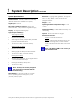
1 System Description The Manning GM-1 is designed to accept a single 4/20 mA current input signal, plus provide a regulated 24 VDC supply to operate all sensors manufactured by Honeywell Analytics. The Manning GM-1 is housed in a rugged 14 gauge gasketed steel enclosure. Behind the clear plexiglass window is a 20-segment vertical LED bargraph display which gives a visual indication of the gas concentration.
1 System Description continued System Specifications Electrical Power: 120 VAC, 50/60 Hz at 0.35 amp (230 VAC 50/60 Hz is available as an option) Signal input: 4/20 mA DC Power available for sensors: Heavy-duty internal 24 VDC, 1 amp maximum regulated supply Enclosure: 14 gauge steel, gasketed, 10" high x 8" wide x 4" deep, NEMA 1 rated enclosure with plexiglass window Weight: 11 lbs.
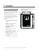
2 A Installation Locating the Manning GM-1 When unpacking the unit, inspect all boxes and contents for shipping damage. If any screws or other metal parts are missing, these must be found to ensure that the printed circuit boards will not be damaged when power is applied. Figure 1: Mounting dimensions for the Manning GM-1 Gas Monitoring Alarm System 6" 5/16" The control unit is designed to be mounted on a solid (non-vibrating) wall through four holes in the two mounting flanges.
2 B Installation continued Wiring Electrical wiring must comply with all applicable codes. Plant equipment that may be involved and operating conditions should be discussed with local operating personnel to determine if any special needs should be taken into account. Relay Wiring: All three relays have Form C, dry contacts. Any required power source must be within the 3 amp rating and fused or current limited to keep from damaging the contacts.
2 Installation continued Figure 2: Wiring diagram for the Manning GM-1 Gas Monitoring Alarm System WARNING ADJUST TP +20V ALARM ADJUST BOT TOP 7 TP WARNING TP ALARM TP SIG ALARM RELAY FAULT RELAY TP CURRENT WARNING RELAY DRAW TP GND 1 6 + C11 + + FUSE RATING 250V 1.0 AMP SHLD GND L N 120 VAC NO C NC WARNING RELAY* NO C NC NO ALARM RELAY* C + 24 SIG NC FAULT RELAY* MODEL G/M MAINBOARD REV D *Relay rating 3 amp. User must fuse to protect.
3 A Operation Display Panel A 20-segment Bargraph Display indicates the gas concentration level. The bottom LED is always lit to indicate power to the display. The Warning LED indicates the warning level as determined by the warning setpoint has been exceeded. The Warning LED and Warning Relay operate together and never latch. The Alarm LED indicates the alarm level as determined by the alarm setpoint has been exceeded.
3 D Operation continued Signal and Setpoints The voltage between TP Gnd and TP Sig indicates the current signal received from the sensor. The normal range is 0.4 volts to 2.0 volts, which corresponds with 4/20 mA. This manual will use the voltage at TP Sig to describe the input signal. When this signal exceeds the voltage at TP Warning or TP Alarm, the warning or alarm function will take place.
3 Operation continued Maintenance G Replacement Parts H The Manning GM-1 is designed for long life and high reliability. Honeywell Analytics recommends checking signal voltages monthly and logging them on the data sheet included with your Manning GM-1. Additionally, the sensor being monitored should be exposed to the target gas on a monthly basis while all alarm functions are verified at the Manning GM-1.
4 1. 2. Limited Warranty Limited Warranty Honeywell Analytics, Inc.