
Datasheet


6
sensing.honeywell.com
TL Series
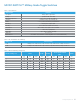
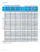
TERMINAL CIRCUIT IDENTIFICATION
Terminal identications are referred to in the order guides to indi-
cate which circuits are made in each toggle position (i.e., 1-2 refers
to circuit closure through terminals 1 and 2).
One Pole
Two Pole
Four Pole
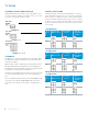
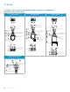
TERMINALS
In addition to the screw terminal listings in the order guides, IWTS
(Integrated Wire Termination Systems) versions and solder turrent
terminals are available.
IWTS provides a reliable, completely serviceable unit which meets
MIL-DTL-3950 requirements. IWTS improves maintainability since
wiring bundles need not be disturbed. Leads are quickly and easily
assembled or removed with an insert-extract tool.
A unique three-rib (grommet style) elastomer seal protects the lead
connections without potting. There are no exposed metal termi-
nals.
Versions available that will accept No. 16 wire with M39029/1-102
contact pins or No. 20 wire with MS39029/1-101 contact pins.
Connections are resistant to shock, vibration, and high pull-out
force.
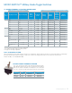
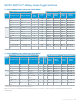
SPECIAL CIRCUITRIES
Catalog listings with -10, -50, and -70 sufx numbers, as shown
in the order guides, have special “on-on-on” circuits, as illustrated
below. TLs with -12 sufx are the same as -50 except the keyway
position is maintained, and the center position circuits 2-3 and 4-5
are made. -72 is the same as -50 except that the opposite keyway
position is momentary, and in the center position circuits 2-3 and
4-5 are made.
-10 CIRCUITRY
No of
poles
Keyway Side
Maint. Position
Center Maint.
Position
Opposite
Keyway Maint.
Position
2
4
-50 CIRCUITRY
No of
poles
Keyway Side
Maint. Position
Center Maint.
Position
Opposite
Keyway Maint.
Position
2
4
-70 CIRCUITRY
No of
poles
Keyway Side
Maint. Position
Center Maint.
Position
Opposite
Keyway Maint.
Position
2
4