
Submittal Sheet
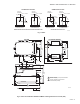
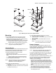


Table Of Contents
SERIES 41 AND 81 MODUTROL IV™ MOTORS
63-2627—01 10
OPERATION AND CHECKOUT
Operation
In an operational circuit, a single-pole, single-throw controller
or fan starter (line voltage for Series 41, or low voltage for
Series 81) is wired in series with the motor circuit. When the
controller switch closes, the motor is energized and runs to the
end of its stroke. When the motor reaches it full stroke, it holds
this position as long as it is energized. When the controller
opens, the spring returns to the starting position.
Checkout
After the installation is complete, check the entire system for
the following points of operation:
• Motor operates the load properly.
• Motor responds properly to the controller.
• Motor returns to starting position when power is interrupted.
Damper Application
1. Check the entire motor-damper linkage to ensure that
the mechanical connections are secure and properly
made. Be certain the ball joint on the damper crank arm
is properly placed to give the required amount of travel.
2. Energize the motor and run it to the end of its stroke.
Check the damper linkage while the motor is running to
see that there are no loose or binding connections.
3. If the motor does not run, check the control circuit for an
open or short, the presence of power, and voltage at the
motor. Voltage at the motor must be at least 85 percent
of the rated voltage (specified on nameplate.) Ensure
that the maximum motor net load is not exceeded.
4. Interrupt the power to de-energize the motor and allow
the spring to return the motor to the starting position. If
the motor does not return, check to ensure that power is
actually interrupted and that the return load is not
exceeding the rated motor load.
Valve Application
1. Check entire motorized valve assembly to ensure that
the mechanical connections (among motor, linkage, and
valve) are proper and secure. Be certain that the linkage
is adjusted according to the linkage instructions. Leave
the linkage cover off until the checkout is completed.
2. Be certain the load does not exceed the motor rating.
When using a Q5001 Linkage, no lubrication is required.
Install the plastic washer on the motor shaft between the
motor and cam to avoid motor binding and stalling.
Check to ensure that the linkage spring
compression is within the limits specified in the Q5001
Installation Instructions.
3. Energize the motor by setting the controller so that its
contacts close.
NOTES:The motor should start and run smoothly,
moving the valve stem to the opposite end of its
stroke. If this is not the case:
—Ensure there is power to the motor.
—If there is not power, check the controller
circuit for open or short circuits.
—If the trouble still cannot be found, measure
the voltage at the source.
—Line voltage must be at least 85 percent of
rated voltage stamped on motor nameplate.
4. De-energize motor by resetting the controller so its
contacts open, or remove one wire from a controller
terminal. Spring power should return the valve to normal
position. If this does not happen, check the linkage for
binding, or in the case of normally closed valves, check
for fluid pressure in excess of the close-off rating.
5. Replace the linkage cover.
REPLACEMENT
Damper Application
1. Turn off power and remove wiring from the old motor.
2. Remove crank arm from the old motor shaft and remove
the old motor.
3. Check to determine whether or not the mounting bracket
is needed. If the linkage can reach the new motor lower
shaft position and the crank arm has clearance for the
necessary rotation, then the bracket is not required. Use
the 220738A Adapter Bracket or the 221455A Crank
Arm if the crank arm must rotate through the motor
bottom plane.
4. If no bracket is required, mount the new motor directly to
the equipment and refer as necessary to Installation,
Settings and Adjustments, and Operation and Checkout
sections of these instructions.
5. If the bracket is required, refer to the Adapter Bracket
section and see Fig. 3 in addition to the Installation,
Settings and Adjustments, and the Operation and
Checkout sections of these instructions.
6. Use old mounting bolts to mount the new motor.
7. Mount the damper crank arm and linkage to the shaft of
the new motor.
8. Use the Checkout procedures to test proper adjustment
of the crank arm and linkage.
Valve Application
When replacing a motor in a valve application that has a Q100,
Q601 or Q618 Linkage, it will be necessary to use the
220738A Adapter Bracket provided to raise the motor shaft to
the same height as that of the old motor. In valve applications
that have a Q5001 Linkage, the 220738A Adapter Bracket is
unnecessary. Ensure motor stroke is 160° to operate
Honeywell V5011 Two-way or V5013 Three-way Valves.