
Submittal Sheet
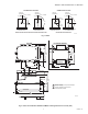
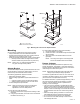
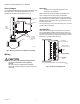


Table Of Contents

SERIES 41 AND 81 MODUTROL IV™ MOTORS
5 63-2627—01
Fig. 3. Mounting the motor with an adapter bracket.
Mounting
Use the following guidelines for proper motor mounting:
• Always install motors with the crankshaft horizontal.
• Mounting flanges extending from motor housing base are
drilled for 6.4 mm machine screws or bolts.
• Motors are shipped from the factory in their normal position:
— Normally closed models are shipped at the counter-
clockwise rotation limit (viewed from the power end).
NOTE: Refer to Fig. 1 for graphical representation of
fully-open and fully-closed positions.
Adapter Bracket
The 220738A Adapter Bracket, positioned between the motor
and the equipment, raises motor shaft height by 19 mm to
match that of previous Modutrol Motor models.
The following applications require this bracket:
• Q607 External Auxiliary Switch.
• Damper linkage applications require added clearance to
allow:
— Crank arm rotation through the downward position.
— Sufficient damper linkage to reach the motor shaft.
• All valve linkages except the Q5001.
NOTE: When the bracket is not used in a replacement
application, the damper linkage can require
adjustment for the new shaft position.
To mount the motor with the bracket:
1. Mount the bracket to the equipment with existing or stan-
dard bolts.
2. Using the provided bolts, mount the motor to the bracket
threaded holes. See Fig. 3.
For valve linkage applications (other than the Q5001):
1. Mount the bracket to the linkage.
2. Position the motor on the bracket to align the motor shaft
with the linkage.
3. Attach the motor to the bracket with the four bolts
(provided).
NOTE: The bolts go through the motor flange holes
and into the threaded holes of the bracket.
Damper Linkages
Use of the 220738A Adapter Bracket is optional for many
damper applications. This bracket or a 221455A Crank Arm
might be needed in applications that require the crank arm to
rotate through the motor bottom plane.
NOTE: Replacement applications where the shaft height
changes require damper linkage adjustment.
The motor is supplied without a crank arm. The crank arm is
included in the Q605 Linkage or can be ordered separately
(see Accessories in the Specifications section).
For detailed instructions on specific linkage assembly, refer to
the instruction sheet packed with the linkage. In general,
however, check the following points of operation when
installing a motor and linkage:
— The motor must be permitted to complete its full stroke.
Damper or valve induced motor stall can damage the motor.
Adjust valve and louver-type damper linkages so that the
damper or valve moves through no more than the maximum
required distance when the motor moves through its full
stroke.
— Maximum damper opening should be no more than 60°.
Little additional airflow is provided beyond this point.
— Do not exceed the motor ratings in any installation.
— Do not turn the motor shaft manually or with a wrench.
This damages the motor.
EQUIPMENT
BASE
ADAPTER
BRACKET
STANDARD
BOLTS (4)
MOTOR
BOLTS
PROVIDED (4)
WIRING
BOX
1 #12 OR 1/4" ZINC PLATED
MACHINE SCREWS OR BOLTS
1
POWER
END
POWER END
M18993