
Submittal Sheet
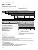
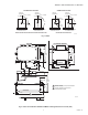
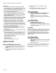
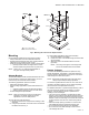
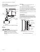


Table Of Contents

SERIES 41 AND 81 MODUTROL IV™ MOTORS
63-2627—01 6
Valve Linkages
Use the 220738A Adapter Bracket with the Q100 Linkage in all
valve applications. The 220738A Adapter Bracket is not
required with the Q5001 Valve Linkage (see Fig. 4).
Fig. 4. Mounting the motor on a Q5001 valve linkage.
Wiring
CAUTION
Electrical Shock or Equipment Damage Hazard.
Can shock individuals or short equipment
circuitry.
Disconnect all power supplies before installation.
Motors with auxiliary switches can have more than one
disconnect.
IMPORTANT
All wiring must comply with applicable codes,
ordinances and regulations.
Make sure that the voltage and frequency stamped on the
motor correspond to the power supply characteristics.
Fig. 5 shows the motor terminals (quick-connects located on
top of the printed circuit board). Wiring compartment access is
gained by removing the four screws from the junction box top
and lifting off the cover.
See Fig. 6 through 10 for typical system wiring. Fig. 12 shows
auxiliary switch connections.
Junction Box
When used with liquid-tight conduit connectors, the junction
box provides NEMA 3 weather protection for the motor. The
box also provides knockouts for wiring conduits and encloses
terminals. The junction box is required for housing an internal
transformer or internal auxiliary switches.
Fig. 5. Terminals and adjustments.
1/4-20 UNC
1 in. LONG
MOUNTING
BOLTS
Q5001
VALVE
LINKAGE
M18994
MOTOR
JUNCTION
BOX
POWER
END OF
MOTOR
VALVE
RIGHT INNER
AUXILIARY SWITCH
INNER AUXILIARY
SWITCH CAM (BLUE)
POWER
END
OUTER AUXILIARY
SWITCH CAM (RED)
LEFT OUTER
AUXILIARY
SWITCH
NOTE: FEATURES AVAILABLE ON SOME MODELS ONLY.
M18995
T2
T1