
Submittal Sheet
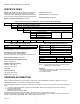
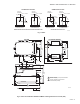
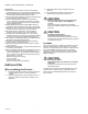
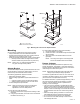
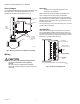


Table Of Contents

SERIES 41 AND 81 MODUTROL IV™ MOTORS
63-2627—01 8
SETTINGS AND ADJUSTMENTS
Before Setting Stroke
1. Remove the top cover from the motor.
2. Disconnect the controller from the motor.
3. For models with an internal transformer (line voltage
motors), ensure that power (and nothing else) remains
connected to the motor.
IMPORTANT
Detach linkage from motor before adjusting stroke.
Adjustable Stroke
When viewing from the power end of the motor, the stroke
potentiometer is to the far left. To set the stroke to 160°
(maximum position) turn the potentiometer fully clockwise
, using a 1/8 in. straight-blade screwdriver. To set the
stroke at 90° (minimum position) turn the potentiometer fully
counter-clockwise . Setting the potentiometer anywhere
between fully clockwise and fully counter-clockwise will set the
stroke between 160° and 90°.
Fig. 11. Stroke adjustments.
CAUTION
Careless Installation Hazard.
Use of excessive force while adjusting cams
damages the motor.
To avoid damaging motor end switches, set cams by
moving only the screwdriver top.
CAUTION
Equipment Damage Hazard.
Can damage the motor beyond repair.
Never turn the motor shaft by hand or with a wrench.
Forcibly turning the motor shaft damages the gear train
and stroke limit contacts.
Auxiliary Switches
The auxiliary switches are spdt switches that are actuated by
adjustable cams. The cams are factory-mounted on the motor
shaft at the power end of the motor. The cam settings
determine the point in motor shaft rotation at which the
auxiliary equipment will be switched on or off. These cams can
be set to actuate the switches at any angle within the motor
stroke.
NOTE: Series 2 Motors are shipped with auxiliary switch
cams that permit acceptance of 220736A,B Internal
Auxiliary Switch Kits. Refer to Form no. 63-2228 for
220736A,B Installation Instructions.
For auxiliary switch wiring, see Fig. 12.
With a 1° differential, the N.C. switch contacts make and the
N.O. switch contacts break on a counterclockwise (closed)
rotation. If a 10° differential is chosen, the operation is
reversed, the N.O. switch contacts make and the N.C. switch
contacts open on a counterclockwise (closed) rotation.
NOTE: When the slow-rise portion of the cam is used, the
switching differential is approximately 10° of rotation.
When the fast-rise portion of the cam is used, the
switching differential is approximately 1° of rotation.
Do not use the fast rise portion of the cam if fast
cycling of auxiliary equipment is undesirable.
Switching action is different depending on whether 1° or 10°
differential is chosen. See Table 4.
Fig. 12. Auxiliary switch schematic.
WARNING
Fire or Explosion Hazard.
Incorrect auxiliary switch wiring can allow the
burner to come on at high fire causing severe
injury or death.
Check auxiliary switch wiring and cam adjustment
before turning on the system.
Watch controlled equipment through a complete cycle.
Shut the system down immediately if switches do not
sequence the equipment correctly.
M13699
POWER END
OF MOTOR
AUXILIARY
SWITCH CAMS
ADJUSTABLE
STROKE
POTENTIOMETER
BLUE LEAD
YELLOW LEAD
RED LEAD
USE NEC CLASS 1 WIRING UNLESS POWER SUPPLY
MEETS CLASS 2 REQUIREMENTS. TAPE UNUSED LEADS.
ENSURE THE CURRENT DRAW OF THE EXTERNAL CIRCUIT
IS LESS THAN SWITCH CONTACT RATING.
ON TWO-SWITCH MOTORS, SECOND SWITCH HAS BLACK
LEADS WITH BLUE, YELLOW, AND RED TRACERS.
SOME AUXILIARY SWITCH ASSEMBLIES INCLUDE ONLY
RED AND YELLOW LEADS. SOME OTHERS DO NOT INCLUDE
THE YELLOW LEAD.
M17099
1
1
1
2
2
2
2
3
3