
Submittal Sheet
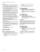
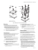
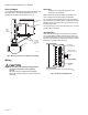


Table Of Contents

SERIES 41 AND 81 MODUTROL IV™ MOTORS
9 63-2627—01
Auxiliary Switch Adjustment
Adjustable cams actuate the auxiliary switches. These cams
can be set to actuate the switches at any angle within the
stroke of the motor. Select switch differential of 1° or 10°.
NOTES:
— Auxiliary switches can only be added to motors
that include auxiliary switch cams. (These cams
cannot be field-added.)
— Normally Closed motors are shipped in the closed
position (counterclockwise, viewed from the power
end) with auxiliary switch cams set to
operate switches 30° from closed position with a 1°
differential. With motor in fully closed position, the
N.C. auxiliary switch contacts are closed.
— See Fig. 12 (or the auxiliary switch Instruction
Sheet) for auxiliary switch wiring.
— Motors are shipped with auxiliary switch cams.
To rotate a cam, insert a small screwdriver (1/8 in. or 3 mm
blade) through the junction box into the slot on the cam and
move the screwdriver at the top of the handle. The inner cam
actuates the right switch and the outer cam actuates the left
switch (viewed from the power end). Refer to Fig. 11. Each
division on the cam represents 15° of motor rotation.
1. Turn off the power and remove the junction box cover.
2. Determine the amount of shaft rotation, in degrees,
desired before the switch is to be energized.
3. Note the cam slot positions.
4. With a screwdriver, rotate the cam to the desired angle
for switching action. As noted above, each cam division
represents 15° of motor rotation. Therefore, if 60° of
motor rotation is desired before the switch operates,
rotate the cam four divisions from the reference point.
5. Turn on the power.
6. Check for proper switch differential and switching of aux-
iliary equipment by driving the motor though full stroke
(in both directions). If necessary, repeat steps 3 and 4
until correct switching action is obtained, turning off the
power before readjusting the cam.
7. When adjustments are complete, replace the junction
box cover.
Fig. 13. Auxiliary switch adjustments.
Table 5. Auxiliary Switch Position with Motor Shaft Rotated to Either Side of Auxiliary Switch Operating Point
Switch
Differential
Auxiliary Switch Contact Positions (Viewed from the Power End)
N.O. Contact N.C. Contact
Shaft Rotated ccw of
Switch Point
Shaft Rotated cw of
Switch Point
Shaft Rotated ccw of
Switch Point
Shaft Rotated cw of
Switch Point
1° Open Closed Closed Open
10° Closed Open Open Closed
RIGHT/INNER
AUXILIARY
SWITCH
FAST RISE
PORTION
(APPROX.
1 DIFF.)
SLOW RISE
PORTION
(APPROX.
10 DIFF.)
INNER
AUXILIARY
CAM
(BLUE)
NOTE: CAMS ARE OFFSET
VERTICALLY TO PROVIDE
BETTER VIEW OF BACK CAM.
FAST RISE
PORTION
(APPROX.
1 DIFF.)
SLOW RISE
PORTION
(APPROX.
10 DIFF.)
MOTOR
OPEN
MOTOR
CLOSE
POWER
END
OUTER
AUXILIARY
CAM
(RED)
LEFT/OUTER
AUXILIARY
SWITCH
M17101
POWER END
OF MOTOR
OUTER AUXILIARY
CAM (RED)
INNER AUXILIARY
CAM (BLUE)
RIGHT/INNER
AUXILIARY SWITCH
LEFT/OUTER
AUXILIARY
SWITCH
MOVE SCREWDRIVER AT
TOP ONLY TO ADJUST CAM.
1/8 INCH
STRAIGHT-BLADE
SCREWDRIVER