
Install Instructions


® U.S. Registered Trademark
Copyright © 1997 Honeywell Inc. • All Rights Reserved
INSTALLATION INSTRUCTIONS
X-XX UL
7800 Series
221818A,C Extension Cable Assembly
APPLICATION
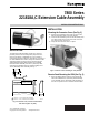
The Extension Cable Assembly consists of a cover that
provides protection for the configuration jumpers and the
plug-in purge timers, if applicable. The cover contains a
connector that interfaces with the computer bus connector of
the 7800 SERIES device which, through the attached cable
assembly, provides connection to the remotely-mounted
S7800 Keyboard Display Module (KDM). The 221818A
Extension Cable Assembly has a 60 in. (1524 mm) cable
assembly; the 221818C Extension Cable Assembly has a
120 in. (3048 mm) cable assembly. See Fig. 1.
Fig. 1. Connector cover, connector dimensions,
and cable length in in. (mm).
INSTALLATION
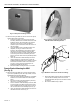
Mounting the Connector Cover (See Fig. 2)
1. Align the two interlocking ears of the connector cover
with the two mating slots on the relay module.
2. Insert the two interlocking ears into the two mating slots
and, with a hinge action, push on the lower corners of
the connector cover to secure it.
3. Verify that the connector cover is in place.
Fig. 2. Connector cover mounting on relay module.
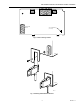
Remote Panel Mounting the KDM (See Fig. 3)
1. Mount the KDM remotely from the relay module with
either the 221818A 60 in. (1524 mm) Cable Assembly
or the 221818C 120 in. (3048 mm) Cable Assembly, on
the face of a panel door or on another remote location.
M10452A
(4)
(23)
BURNER CONTROL
221818A — 60 IN. (1524 MM) CABLE ASSEMBLY
221818C — 120 IN. (3048 MM) CABLE ASSEMBLY
UP
2-3/4
(69)
5/32
29/32
4-27/32 (123)
19/32
(15)
1-11/32
(34)
1
1
65-0131-3