
Datasheet


4 sensing.honeywell.com
MICRO SWITCH™ Miniature Safety Switches, 24CE Series
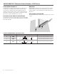
GANG-MOUNT CAPABILITY
The 24CE Series housing has been designed to enable the user
to build their own multiple plunger switch by gang mounting
several switches. All pin plunger and roller plunger types are
suitable for gang mounting. There is a 16 mm distance between
the plungers. The Series is very versatile such that even a lever-
type version could be added at the end of the row.
BOTTOM-EXIT OR SIDE-EXIT ORIENTATION
The 24CE Series has been designed with a pre-wired cable fitted
in the bottom of the switch housing. Other variations are available
with a side-exit cable.
MOUNTING
MICRO SWITCH™ 24CE Series safety switches are mounted by
using two M5 or #10 screws. The mounting holes are counter
bored to keep the screw heads within the overall switch housing
dimensions.
APPLICATION ILLUSTRATION
Two 24CE roller plunger switches to monitor gate position, closed
or open.
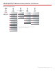
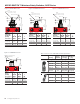
CONTACT ARRANGEMENT AND DESCRIPTION
Circuit Type Circuit Diagram Cable/Connector
S BBM
Brown
Blue
Black
Black*
Green
5 x 0,75 mm
2
harmonised Cenelec cable
T MBB
5 x 0,75 mm
2
harmonised Cenelec cable
Y SPNC
Brown
Blu
e
Green
3 x 0,75 mm
2
harmonised Cenelec cable
* Grey with PUR cable.