
Overview of Primary Product


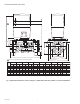

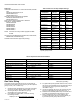
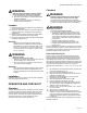

Table Of Contents

V5097A-E INDUSTRIAL GAS VALVES
65-0230—08 10
Table 6. V5097 Valve Allowable Leakage Rate.
a
Based on air at standard conditions, test pressures provided
by ANSI Z21.21, Section 2.42 and a maximum of 235
cc/h/in. of seal-off diameter (not pipe size).
Fig. 5. Valve leak test.
NOTE: For international leak test requirements, contact the
appropriate approval agency.
After the Test
1. Close the upstream manual gas cock (A).
2. Close the test petcock (F), remove the test apparatus,
and replace the leak test tap (D).
3. Open the upstream manual gas cock (A) and energize
the V5097 Valve actuator through the safety system.
4. Test with rich soap and water solution to make sure there
is no leak at the test tap (D) or any pipe
adapter/valve mating surfaces.
5. De-energize the V5097 Valve (C).
6. Open the downstream manual gas cock (E).
7. Restore the system to normal operation. If two safety
shutoff valves are used, check each V5097 Valve for clo-
sure tightness.
SERVICE INFORMATION
WARNING
Explosion Hazard And Electrical Shock Hazard.
Can cause explosion, serious injury or death.
1. Turn off the gas supply and disconnect all electrical
power to the valve actuator before servicing.
2. Properly position and seat the seals in the valve
body to prevent a hazardous gas leak.
3. Do not disassemble the valve bonnet assembly
because the valve seat is not replaceable.
IMPORTANT
Only trained, experienced flame safeguard control
technicians should attempt to service or repair flame
safeguard controls and burner assemblies.
Scheduled Inspection and
Maintenance
Set up and follow a schedule for periodic inspection and
maintenance for the burner, all other controls, and the valve(s)
and actuator(s) for leaking oil. It is recommended that the valve
leak test in the Operation and Checkout section be included in
this schedule. Refer to the instructions for the primary safety
control for more information.
Valve Checkout for Oil Leakage from
Actuator
1. Turn off the gas supply at the manual shutoff valve
located upstream from the valve(s) being serviced.
2. Shut off all electrical power to the valve actuator(s).
3. Mark and disconnect the wires from the actuator termi-
nals. Remove conduit and disengage the damper link-
age assembly (if applicable).
4. Loosen the two set screws from the valve to lift off the
actuator.
5. If the actuator is to be replaced and it did not leak
hydraulic fluid, skip to Step 11.
NOTE: It is good practice to inspect the inside of the
valve whenever the actuator is replaced. To do
so, remove the bonnet assembly, inspect the
valve and bonnet. If all is well, proceed to Step 7.
6. If the actuator leaked hydraulic fluid onto the valve (the
fluid is red), it must be cleaned off from the valve and
bonnet assembly.
a. Wipe off the outer valve body.
b. Remove the valve bonnet bolts and lift off the bonnet.
NOTE: V5055/V5097C and E Valves have additional
internal springs that will push the bonnet up as
the bolts are loosened.
c. Inspect the inside of the valve.
IMPORTANT
If fluid is present on the inside surfaces of the valve
body or bonnet surfaces, the bonnet assembly or
entire valve must be replaced. For part numbers, see
Table 5.
V5097
Pipe
Adapter
Size (in.) Medium
Allowable
Leakage
SCCH
Maximum
No. of
Bubbles in
10 sec. )
Minimum
No. of
Seconds
for 10
bubbles
3/4, 1,
1-1/4,
1-1/2, 2
0.64 gas 573 14 6.7
1.00 air
a
458 9 10.2
1.57 LP 366 9 10.5
2, 2-1/2, 3 0.64 gas 940 24 4.1
1.00 air
a
752 16 6.2
1.57 LP 602 15 6.4
M9547F
GAS
SUPPLY
UPSTREAM
MANUAL
GAS COCK
DOWNSTREAM
MANUAL
GAS COCK
BURNER
DABC E
F
PRV
MANUAL
TEST
PETCOCK
SSOV
1/4 IN. (6 MM)
FLEXIBLE
TUBING
1/4 IN. (6 MM)
ALUMINUM OR
COPPER PILOT
TUBING
JAR OR GLASS
WITH WATER
CUT AT
45 DEGREE
ANGLE
CAN ALSO BE A PERMANENT PETCOCK.
PRV = PRESSURE REGULATING VALVE.
SSOV = SAFETY SHUTOFF VALVE.
USE ONLY ONE OF THE DOWNSTREAM TAPS ON THE SS0V.
1
2
3
4
4
2 3
1
1
2
(13 MM)
LEAK
TEST
TAP