
Overview of Primary Product


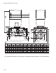

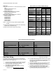
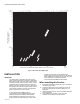

Table Of Contents

V5097A-E INDUSTRIAL GAS VALVES
65-0230—08 6
Approvals:
Underwriters Laboratories Inc. Listed: File MH1639, Guide No.
YI02:
V4055A,B,D,E/V5097A,B,C,D,E.
V4062/V5097A,B,C,E.
V9055/V5097A,B,C,E.
Swiss Re (Formerly GE Gap/IRI) Acceptable:
V4055A,B,D,E/V5097A,B,C,D,E.
V9055/V5097A,B,C,E.
Factory Mutual Approved: Report No. 1D9A2.AF
CSA File No. 158158-1205788
V4055A/V5097A,B.
V4055B/V5097D.
V4055DV5097C.
V4055E/V5097E.
V4062/V5097B,C.
V9055/V5097B,C.
NOTE: CSA does not certify models equipped with BSP
threads.
CE Approved: CE-0063AR1359 (V5097A1020, V5097A1038,
V5097B1028, V5097B1036 Only).
Australian Gas Association Approved (Pending).
Table 4. Valve Plus Two Pipe Adapters Ratings.
Gas Valve Sizing
Honeywell gas valve capacities are shown in cubic feet per
hour (cfh) or cubic meters per hour (m
3
h) for gas with a specific
gravity of 0.64 (1 cfh = 0.0283 m
3
h).
1. Check the burner nameplate for (a) the type of gas used,
and (b) the gas flow capacity (listed in Btuh or in cfh).
2. Call the gas utility for information on (a) sp gr
and (b) Btu/cu ft for type of gas used.
3. If the capacity is listed in Btuh, convert to cfh using
the following formula:
Capacity in cfh = Btuh (from burner nameplate)
Btu/cf (from gas utility)
4. For gases with specific gravities other than 0.64, correct
the cfh from the nameplate or from the formula in step 3
for the specific gravity of gas used, following the
information in Fig. 3.
5. Use the cfh capacity (for 0.64 or the corrected cfh from
step 4) for determining the gas valve size in Fig. 4.
6. Determine the available pressure drop across the valve
and draw a horizontal line at this pressure in Fig. 4.
7. Draw a vertical line in Fig. 4 at the capacity (cfh)
previously determined. Use the corrected capacity for
a gas with a specific gravity other than 0.64.
Adapter
Part Number Size (in.)
CSA Rated Capacity*
(cfh) (cu m/hr)
32000109-001 3/4 NPT 665 18.8
32000109-002 1 NPT 960 27.2
32000109-003 1-1/4 NPT 1406 39.8
32000109-004 1-1/2 NPT 1717 48.6
3200109-005 2 NPT
(Small Body)
1990 56.9
32001605-001 2 NPT
(Large Body)
3620 102.5
32001605-002 2-1/2 NPT 4250 120.3
32001605-003 3 NPT 5230 148.1
32000109-006 3/4 BSP 665 18.8
32000109-007 1 BSP 960 27.2
32000109-008 1-1/4 BSP 1406 39.8
32000109-009 1-1/2 BSP 1717 48.6
32000109-010 2 BSP
(Small Body)
1990 56.9
32001605-004 2 BSP
(Large Body)
3620 102.5
32001605-005 2-1/2 BSP 4250 120.3
32001605-006 3 BSP 5230 148.1
* At 1 in. W.C. (2.5 mbar) Pressure drop; based on gas with
specific gravity of 0.64.
Table 5. Replacement Bonnet Assemblies.
Valve Model Pipe Adapter Size (in. NPT) Replacement Bonnet Assembly (part no.)
V5097A1004 (On-Off) 3/4, 1, 1-1/4, 1-1/2, 2 (small) 133398AA
V5097A1012 2, 2-1/2, 3 (large) 133417AA
V5097B1002 (Characterized guide) 3/4, 1, 1-1/4, 1-1/2, 2 (small) 133398BA
V5097B1010 2, 2-1/2, 3 (large) 133417BA
V5097C1000 3/4, 1, 1-1/4, 1-1/2, 2 (small) 133398CA
V5097C1018 2, 2-1/2, 3 (large) 133417CA
V5097D1008 3/4, 1, 1-1/4, 1-1/2, 2 (small) 136308AA
V5097D1016 2, 2-1/2, 3 (large) 136307AA
V5097E1005 3/4, 1, 1-1/4, 1-1/2, 2 (small) 136308BA
V5097E1013 2, 2-1/2, 3 (large) 136307BA