
User Guide
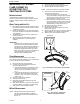
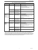
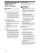
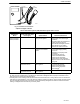


Table Of Contents

FLAME CURRENT
69-1180—1 2
MEASURING PILOT BURNER
FLAME CURRENT ON
INTERMITTENT PILOT
SMARTVALVE® SYSTEMS
Models Included
Intermittent Pilot SmartValve Systems include:
SV9401, SV9402, SV9403, SV9501, SV9502, SV9503,
SV9601, SV9602, SV9440, SV9540, SV9541 and
SV9640.
When Testing with this Kit…
1. Read these instructions carefully. Failure to follow
the instructions can damage the product or cause
a hazardous condition.
2. Check the ratings given in the instructions and on
the product to make sure the product is suitable for
your application.
3. Troubleshooter must be a trained, experienced
service technician.
4. After completing the measurements, use the
appliance instructions to check the product
operation.
IMPORTANT
Accurate Flame current measurement can be
performed only with the pilot flame lit and the
main flame not lit. When measuring with this kit,
the appliance main burner orifices should be
temporarily plugged while measuring system
flame current. Be sure to remove the temporary
plug and check the appliance for proper
operation after completing the test.
Direct Measurement
NOTE:Direct measurement requires an analog dc
micro-ammeter capable of reading to 0.01 microampere
accuracy. No signal converter required.
1. Disconnect all power to the appliance.
2. Connect the test harness between the valve
control and the pilot burner.
a. Insert the banana plug connected to the valve
side of the test harness into the positive (+)
jack on the dc micro-ammeter as shown in
Fig. 1.
b. Insert the other banana plug connected to the
pilot burner side of the test harness into the
negative (-) jack on the dc micro-ammeter as
shown in Fig. 1.
3. Reconnect power to the appliance.
4. Generate a call for heat.
5. Make sure the pilot flame lights and the main
burner does not light.
6. After the pilot flame is on for ten seconds, read the
dc micro-ammeter. The readings must be steady.
7. Take the action recommended in Table 1.
Millivolt Measurement
NOTE: Millivolt measurement requires a digital
voltmeter capable of reading dc millivolts.
Use the signal converter included with this kit.
See Fig. 2.
1. Disconnect all power to the appliance.
2. Connect the signal converter to the voltmeter.
3. Set the voltmeter to read dc millivolts.
NOTE: The signal converter is not polarity sensitive.
4. Connect the test harness between the valve
control and the pilot burner.
a. Insert the valve side of the test harness
through the female end of the signal converter
connector and into the positive (+) jack of the
digital voltmeter, as shown in Fig. 2.
b. Insert the pilot burner side of the test harness
through the female end of the signal converter
connector and into the negative (-) jack of the
digital voltmeter, as also shown in Fig. 2.
5. Reconnect power to the appliance.
6. Generate a call for heat.
7. Make sure the pilot flame lights and the main
burner does not light.
8. After the pilot flame is on for ten seconds, read the
digital voltmeter. The readings must be steady.
9. Take the action recommended in Table 1.
Fig. 1. Test Harness connected to microammeter.
Fig. 2. Test harness connected to
adapter and digital voltmeter.
MICROAMMETER
M16279
A
TEST
HARNESS
+
+
DIGITAL VOLTMETER
M21021
TEST
HARNESS
SIGNAL
CONVERTER
V
COM