
User Guide
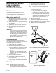
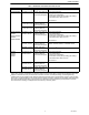
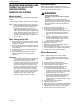


Table Of Contents

FLAME CURRENT
69-1180—1 4
MEASURING MAIN BURNER FLAME
CURRENT ON 120 VOLT HOT
SURFACE IGNITION
SMARTVALVE® SYSTEMS
Models Included
120 Volt Hot Surface Ignition (HSI) SmartValve® systems
include:
SV9410, SV9420, SV9510, SV9520, SV9610, SV9620.
NOTE: Before measure the flame current, check the
appliance installation carefully to make sure that
the 120 volt line input voltage polarity to the
appliance control system is correct. Also,
confirm that the appliance chassis is properly
earth grounded and that the line voltage neutral
wire is reliable connected to earth ground at the
circuit box. The appliance will not operate
properly if the electrical supply and earth ground
are not correct.
When Testing with this Kit…
1. Read these instructions carefully. Failure to follow
the instructions can damage the product or cause
a hazardous condition.
2. Check the ratings given in the instructions and on
the product to make sure the product is suitable for
your application.
3. Troubleshooter must be a trained, experienced
service technician.
4. After completing the measurements, use the
appliance instructions to check the product
operation.
IMPORTANT
Accurate flame measurement can be performed
only with the main burner flame lit after the
ignition system trial for ignition has been
completed. The trial for ignition is the time that
the main gas flows while the HSI element is hot.
Typical trial for ignition times are five to nine
seconds. The appliance will then move to the
Run mode. If If the main burner fails to light,
flame current is not the problem. If the main
burner lights but goes out at the end of the trial
for ignition, recheck appliance power supply
and earth ground. Then check for other
potential problems as directed in Table 2.
Direct Measurement
NOTE:Direct measurement requires an analog dc
micro-ammeter capable of reading to 0.01 microampere
accuracy. No signal converter required.
WARNING
Electrical Shock Hazard.
Can cause serious injury, death or property
damage.
All direct ignition, hot surface ignition (HSI)
SmartValve Systems have line voltage (120 Vac)
present while the hot surface element is powered.
Use extreme caution when the HSI element is
energized.
1. Disconnect all power to the appliance.
2. Connect the test harness between the valve
control and the HSI element/flame rod.
a. Insert the banana plug connected to the valve
side of the test harness into the positive (+)
jack on the dc micro-ammeter as shown in
Fig. 1.
b. Insert the other banana plug connected to
the HSI element/flame rod side of the test
harness into the negative (-) jack on the dc
micro-ammeter as shown in Fig. 1.
3. Reconnect power to the appliance.
4. Generate a call for heat.
5. Make sure the main burner lights and stays on
after the trial for ignition ends.
6. After the main flame is on for ten seconds, read the
dc micro-ammeter. The readings must be steady.
7. Take the action recommended in Table 2.
Millivolt Measurement
NOTE: Millivolt measurement requires a digital
voltmeter capable of reading dc millivolts.
Use the signal converter included with this kit.
See Fig. 3.
1. Disconnect all power to the appliance.
2. Connect the signal converter to the voltmeter.
3. Set the voltmeter to read dc millivolts.
4. Connect the test harness between the valve
control and the HSI element/flame rod.
a. Insert the valve side of the test harness
through the female end of the signal converter
connector and into the positive (+) jack of the
digital voltmeter, as shown in Fig. 3.
b. Insert the HSI element/flame rod side of the
test harness through the female end of the
signal converter connector and into the
negative (-) jack of the digital voltmeter, as also
shown in Fig. 3.
5. Reconnect power to the appliance.
6. Generate a call for heat.
7. Make sure the main burner lights and stays lighted.
8. After the main flame is on for ten seconds, read the
digital voltmeter. The readings must be steady.
9. Take the action recommended in Table 2.