
40003916 Installation Instructions

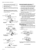

Table Of Contents

40003916 REPLACEMENT POWERHEAD
95C-10665—05 2
1. Switch power supply OFF. Disconnect electrical leads
noting the position and colour of each lead.
2. Place the manual operating lever in the “MAN. OPEN”
position. (See Fig. 1A.)
3. Remove cover. (See Fig. 1B.)
4. Remove the four screws that secure powerhead to the
valve body and remove the powerhead and O-ring. (See
Fig. 2.)
V4043/V4044 incorporates a manual lever, the lever
should normally be in “AUTO” position, but can be
moved to “MAN. OPEN” position for system draindown
and filling purposes only.
Fig. 2. Removing Powerheads
Fig. 3. Installing Replacement Heads
INSTALLING REPLACEMENT HEAD ON OLD STYLE
VALVE BODY (REQUIRES THE ADAPTOR KIT)
1. Insert the new O-ring (supplied with the Adaptor Kit) into
the circular slot on top of the valve body. (See Fig. 3A.)
2. Place the adaptor on the valve body and secure it with
the four hex-nut screws provided - ensuring that the
three guide pins engage in their mating recesses.
3. Place the manual operating lever of the replacement
head in the “MAN. OPEN” position and fit the head onto
the valve body assembly - ensuring that the shaft seats
correctly.
4. Secure the head to the valve body adaptor assembly
with the two screws provided.
5. Reconnect the wiring as shown in Fig. 4.
REMOVING NEW STYLE HEAD FROM NEW STYLE VALVE
BODY (OR OLD STYLE VALVE BODY WITH ADAPTOR)
NOTE: It is not necessary to drain the system if the new
style valve body or old style valve body with
adaptor remain in the pipeline.
1. Switch power supplies OFF. Disconnect electrical leads,
carefully noting the position and colour of each lead.
2. Place the manual operating lever in the “MAN. OPEN”
position. (See Fig. 1A.)
3. Remove cover. (See Fig. 1B.) Remove the two screws
that secure the head to the valve body assembly (Fig.
3A) or to the valve body adaptor assembly. (Fig. 3B.)
INSTALLING NEW STYLE HEAD ON NEW STYLE VALVE
BODY ASSEMBLY (OR OLD STYLE BODY WITH
ADAPTOR ATTACHED)
1. Place manual operating lever on the replacement head
in the “MAN. OPEN” position and fit the head onto the
valve body, ensuring that the shaft seats correctly. (See
Fig. 3B.)
2. Secure the head to the valve body with the two screws
provided.
3. Rewire as shown in Fig. 4.
When replacing the heads of V4043H1056 and V4043H1056-6 zone
valves with replacement head 40003916-001, isolate and make the
white wire safe.
Fig. 4. Wiring Diagram
Old Style Head
Old Style Body
Fig. A. New style head;
old style body (requires
an adaptor kit)
Fig. B. New style head;
new style body
Fig. A. V4043H Head
replacement.
Fig. B. V4044 Head
replacement.