
Install Instructions


63-2522
3
43191679-111/-112 AUXILIARY POTENTIOMETERS
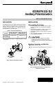
Fig. 6. Routing potentiometer wires to terminal block and connecting to terminals.
C8378
C8377
T Y G
ORANGE
BROWN
VIOLET
PI
Fig. 7. Internal wiring for potentiometer.
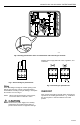
Wiring
Route field wiring in through the conduit opening in the
bottom of the actuator, connect to the potentiometer
terminal block according to the job drawings, and replace
the actuator cover. See Fig. 8.
NOTE: When reversing the direction of the actuator,
reverse the wires to Terminals Y and G.
CAUTION
Disconnect the power supply to the auxiliary
potentiometer and actuator before wiring to
prevent electrical shock or equipment damage.
All wiring must comply with local codes, regulations, and
ordinances.
C8376
T Y G T Y G
Fig. 8. Field wiring for potentiometer.
CHECKOUT
Drive actuator shaft fully up and fully down and check the
operation of the auxiliary potentiometer, e. g., feedback in
the control system or remote indication of the valve
position.