2020/4820/4820i 2D Cordless Imaging System User’s Guide ™
Disclaimer Honeywell International Inc. (“HII”) reserves the right to make changes in specifications and other information contained in this document without prior notice, and the reader should in all cases consult HII to determine whether any such changes have been made. The information in this publication does not represent a commitment on the part of HII.
Product Agency Compliance USA FCC Part 15 Subpart C This device complies with part 15 of the FCC Rules. Operation is subject to the following two conditions: 1. This device may not cause harmful interference. 2. This device must accept any interference received, including interference that may cause undesired operation. Caution: Any changes or modifications made to this equipment not expressly approved by Honeywell may void the FCC authorization to operate this equipment. UL Statement UL listed: UL60950-1.
cUL Statement cUL listed: CSA C22.2 No.60950-1-03 for I.T.E product safety. Europe The CE mark on the product indicates that this device is in conformity with all essential requirements of the 1999/5/EC R&TTE Directive. In addition, complies to 2006/95/EC Low Voltage Directive, when shipped with recommended power supply. For further information please contact: Honeywell Imaging & Mobility Europe BV International Inc.
The crossed out wheeled bin symbol informs you that the product should not be disposed of along with municipal waste and invites you to use the appropriate separate take-back systems for product disposal. If you need more information on the collection, reuse, and recycling systems, please contact your local or regional waste administration. You may also contact your supplier for more information on the environmental performances of this product.
International ! CAUTION: RISK OF EXPLOSION IF BATTERY IS REPLACED BY AN INCORRECT TYPE. The battery should be disposed of by a qualified recycler or hazardous materials handler. Do not incinerate the battery or dispose of the battery with general waste materials. Eye Safety Statement LED This device has been tested in accordance with IEC60825-1 LED safety, and has been certified to be a Class 1 LED device.
Solids and Water Protection The 4820 has a rating of IP41, immunity of foreign particles and dripping water. The 4820i has a rating of IP54, immunity of foreign particles and sprayed water. Patents Please refer to product packaging for patent information.
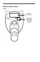
Required Safety Labels Scanner Compliance Label locations Item Number, Serial Number and Revision Information location
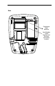
Base Compliance Label locations Item Number, Serial Number and Revision Information location
Table of Contents Chapter 1 - Getting Started About This Manual ...................................................... 1-1 Unpacking the System ................................................ 1-1 Image Scanner Models ............................................... 1-1 Cordless System: Main Components .......................... 1-2 About the Battery ........................................................ 1-2 Proper Disposal of the Battery .................................... 1-3 Connecting the Base .......
Keyboard Modifiers....................................................2-13 RS-232 Baud Rate .............................................. 2-16 RS-232 Word Length: Data Bits, Stop Bits, and Parity ...................................................... 2-16 RS-232 Receiver Time-Out ................................ 2-17 RS-232 Handshaking .......................................... 2-18 Host ACK Selection ............................................ 2-18 Host ACK Enable ........................................
Single Image Scanner Operation ................................ 3-5 Locked Link Mode - Single Image Scanner .......... 3-6 Open Link Mode - Single Image Scanner ............ 3-6 Override Locked Image Scanner .......................... 3-6 Multiple Image Scanner Operation.............................. 3-7 Image Scanner Name ................................................. 3-7 Image Scanner Report ................................................ 3-9 Application Work Groups ...................................
Good Read Delay ........................................................4-3 User-Specified Good Read Delay................................4-3 Serial Trigger Modes ...................................................4-4 Manual/Serial Trigger, Low Power ........................ 4-4 Scan Stand Mode ........................................................4-6 Scan Stand Symbol .............................................. 4-6 Presentation Mode.......................................................
Chapter 5 - Data Editing Prefix/Suffix Overview ................................................. 5-1 To Add a Prefix or Suffix: ..................................... 5-1 To Clear One or All Prefixes or Suffixes: .............. 5-2 To Add a Carriage Return Suffix to All Symbologies .............................................. 5-3 Prefix Selections ................................................... 5-4 Suffix Selections ................................................... 5-4 Function Code Transmit .......
Code 93 ..................................................................... 7-11 Code 93 Code Page ........................................... 7-11 Straight 2 of 5 Industrial (three-bar start/stop) ........... 7-12 Straight 2 of 5 IATA (two-bar start/stop) .................... 7-13 Matrix 2 of 5 ............................................................... 7-14 Code 11 ..................................................................... 7-15 Code 128 ....................................................
Postal Codes ............................................................. 7-39 Intelligent Mail Barcode ...................................... 7-39 ID-tag (UPU 4-State) .......................................... 7-40 Postnet ............................................................... 7-40 Planet Code ........................................................ 7-41 British Post ......................................................... 7-42 Canadian Post ....................................................
OCR Templates ...........................................................9-3 Creating an OCR Template .................................. 9-3 Stringing Together Multiple Formats (Creating “Or” Statements) .............................. 9-5 OCR User-Defined Variables.......................................9-6 Reading Multi-Row OCR ...................................... 9-7 OCR Check Character.................................................9-7 OCR Modulo 10 Check Character ........................
QuickView ................................................................. 11-6 Installing QuickView from the Web ..................... 11-6 Temporary QuickView Configuration ........................ 11-7 Chapter 12 - Serial Programming Commands Conventions .............................................................. 12-1 Menu Command Syntax............................................ 12-1 Query Commands .............................................. 12-2 Concatenation of Multiple Commands .............
Chapter 14 - Maintenance Repairs ......................................................................14-1 Maintenance ..............................................................14-1 Cleaning the Device ............................................ 14-1 Inspecting Cords and Connectors ...................... 14-1 Replacing the 2020 Interface Cable: .................. 14-2 Assembling the Battery Charge Sleeve Kit................14-3 Troubleshooting the Base..........................................
1 Getting Started About This Manual This User’s Guide provides installation and programming instructions for the 4820/4820i. Product specifications, dimensions, warranty, and customer support information are also included. Honeywell barcode image scanners are factory programmed for the most common terminal and communications settings. If you need to change these settings, programming is accomplished by scanning the barcodes in this guide. An asterisk (*) next to an option indicates the default setting.
Cordless System: Main Components Battery Contained in Handle Image Scanner 2020 Base About the Battery ! We recommend use of Hand Held Products Li-ion battery backs. Use of any non-Hand Held Products battery may result in damage not covered by the warranty. Power is supplied to the cordless image scanner by a rechargeable battery that is integrated in the image scanner handle. Each image scanner is shipped with a battery. (See Product Specifications beginning on page 13-1.
• The battery is a lithium ion cell and can be used without a full charge, and can also be charged without fully discharging, without impacting the battery life. There is no need to perform any charge/discharge conditioning on this type of battery. • Do not disassemble the battery. There are no user-serviceable parts in the battery. • Keep the base connected to power when the host is not in use. • Replace a defective battery immediately since it could damage the image scanner.
1. Connect the appropriate interface cable to the base first and then to the computer. Make sure the cables are secured in the wireways in the bottom of the base and that the base sits flat on a horizontal surface. 2. Program the base for the USB interface by scanning the appropriate programming barcode See page 2-5. 3. Verify the base operation by scanning a barcode from the Sample Symbols in the back of this manual.
2. Connect the appropriate interface cable to the base and to the terminal/ computer and keyboard. Make sure the cables are secured in the wireways in the bottom of the base and that the base sits flat on a horizontal surface. 3. Turn the terminal/computer power back on. 4. Program the base for the keyboard wedge interface. See "Keyboard Wedge Connection" on page 2-1. 5. Verify the base operation by scanning a barcode from the Sample Symbols in the back of this manual.
Connecting the Base with RS-232 Serial Port 1. Turn off power to the terminal/computer. 2. Connect the appropriate interface cable to the base. Make sure the cables are secured in the wireways in the bottom of the base and that the base sits flat on a horizontal surface. Note: For the base to work properly, you must have the correct cable for your type of terminal/computer. 3. Plug the serial connector into the serial port on your computer. Tighten the two screws to secure the connector to the port. 4.
3. Connect the appropriate interface cable to the base. Make sure the cables are secured in the wireways in the bottom of the base and that the base sits flat on a horizontal surface. Note: For the base to work properly, you must have the correct cable for your type of computer. 4. Plug the serial connector into the serial port on your computer. Tighten the two screws to secure the connector to the port. 5. Plug the other serial connector into the host connection and tighten the two screws. 6.
is the first time that the image scanner and base are linked, both devices emit a short chirp when their radios link. At this point, you are set to one image scanner to one base. Image Scanner Green LED Red LED 2020 Base 1. Provide power to the base. 2. Place the image scanner into the base. The image scanner and base link. 3. To determine if your cordless system is set up correctly, scan one of the sample barcodes in the back of this manual.
When data is scanned, the data is sent to the host system via the base unit. The cordless image scanner recognizes data acknowledgement (ACK) from the base unit. If it cannot be determined that the data has been properly sent to the base, the image scanner issues an error indication. You must then check to see if the scanned data was received by the host system.
Linear barcode 2D Matrix symbol The aiming beam is smaller when the image scanner is closer to the code and larger when it is farther from the code. Symbologies with smaller bars or elements (mil size) should be read closer to the unit. Symbologies with larger bars or elements (mil size) should be read farther from the unit.
2 Programming the Interface Introduction Chapter 1 describes connecting the base to the computer with the appropriate interface cable. This chapter describes how to program your system for the desired interface. Programming the Interface - Plug and Play Plug and Play barcodes provide instant image scanner set up for commonly used interfaces. Note: After you scan one of the codes, power cycle the host terminal to have the interface in effect.
RS-232 The RS-232 Interface barcode is used when connecting to the serial port of a PC or terminal. The following RS-232 Interface barcode also programs a carriage return (CR) and a line feed (LF) suffix, baud rate, and data format as indicated below. It also changes the trigger mode to manual.
IBM 4683 Ports 5B, 9B, and 17 Interface Scan one of the following “Plug and Play” codes to program the image scanner for IBM 4683 Port 5B, 9B, or 17. Note: After scanning one of these codes, you must power cycle the cash register.
IBM SurePos Scan one of the following “Plug and Play” codes to program the image scanner for IBM SurePos (USB Handheld image scanner) or IBM SurePos (USB Tabletop imager). Note: After scanning one of these codes, you must power cycle the cash register.
USB PC or Macintosh Keyboard Scan one of the following codes to program the image scanner for USB PC Keyboard or USB Macintosh Keyboard. Scanning these codes adds a CR and LF, along with selecting the terminal ID (USB PC Keyboard - 124, USB Macintosh Keyboard - 125, USB PC Japanese Keyboard - 134). USB Keyboard (PC) USB Keyboard (Mac) USB Japanese Keyboard (PC) USB HID Scan the following code to program the image scanner for USB HID barcode image scanners.
CTS/RTS Emulation CTS/RTS Emulation On * CTS/RTS Emulation Off ACK/NAK Mode ACK/NAK Mode On * ACK/NAK Mode Off Serial Wedge To set up the serial wedge terminal ID, use the serial terminal ID 050 and follow the instructions on page 2-6. Make sure that all of the communication parameters match on all of the connected devices. Scanning Both P1 and P2 sends scanned data to P1 and P2. Default = P1.
For example, an IBM AT terminal has a Terminal ID of 003. You would scan the Terminal ID barcode, then 0, 0, 3 from the Programming Chart inside the back cover of this manual, then Save. If you make an error while scanning the digits (before scanning Save), scan the Discard code on the Programming Chart, scan the Terminal ID barcode, scan the digits, and the Save code again. Note: The default interface is Keyboard Wedge (Term ID = 003).
Supported Terminals Terminal Model(s) DDC DDC DEC DEC 3496, 3497, 122 key 3496, 3497, 102 key VT510, 520, 525 (PC style) VT510, 520, 525 (DEC style LK411) 200, 400 PC, AT Esprit Heath Zenith Heath Zenith HP HP IBM IBM IBM IBM 102 key IBM 122 key IBM 122 key IBM 122 key IBM 122 key IBM DOS/V 106 key IBM SurePOS IBM SurePOS IBM Thinkpad IBM Thinkpad IBM Thinkpad I/O 122 key ITT Lee Data NEC Olivetti Olivetti RS-232 TTL Serial Wedge Silicon Graphics 2-8 Vectra Vectra XT PS/2 25, 30, 77DX2 AT, PS/2 30–286
Supported Terminals Terminal Model(s) Telex 88 key 078, 078A, 79, 80, 191, 196, 1191,1192, 1471, 1472, 1476, 1477, 1483 Data Entry Keyboard 078, 078A, 79, 80, 191, 196, 1191,1192, 1471, 1472, 1476, 1477, 1483 078, 078A, 79, 80, 191, 196, 1191,1192, 1471, 1472, 1476, 1477, 1482, 1483 Telex 88 key Telex 102 key Telex 122 key USB COM Port Emulation USB PC Keyboard USB Mac Keyboard USB Japanese Keyboard (PC) USB HID POS Wand Emulation (Code 39 Format) Wand Emulation (Same Code Format) Terminal ID 025 112 0
Keyboard Country Scan the appropriate country code below to program the keyboard for your country.
Keyboard Country (continued) Italy Latin America Netherlands (Dutch) Norway Poland Portugal Romania Russia SCS Slovakia Spain Sweden Switzerland (German) 2 - 11
Keyboard Country (continued) Turkey F Turkey Q U.K. Please refer to the Honeywell website (www.honeywell.com/aidc) for complete keyboard country support information and applicable interfaces. If you need to program a keyboard for a country other than one listed above, scan the Program Keyboard Country barcode below, then scan the numeric barcode(s) for the appropriate country from the inside back cover, then the Save barcode.
Shift Lock is used when you normally have the Shift Lock key on (not common to U.S. keyboards). Shift Lock Automatic Caps Lock is used if you change the Caps Lock key on and off. The software tracks and reflects if you have Caps Lock on or off (AT and PS/2 only). This selection can only be used with systems that have an LED which notes the Caps Lock status. Automatic Caps Lock Autocaps via NumLock barcode should be scanned in countries (e.g.
support all keyboard country codes. New users should use the Windows mode. Refer to Keyboard Function Relationships, page 10-1 for CTRL+ ASCII Values. Default = Control + ASCII Mode Off Windows Mode Control + ASCII Mode On * Control + ASCII Mode Off DOS Mode Control + ASCII Mode On Turbo Mode: The image scanner sends characters to a terminal faster. If the terminal drops characters, do not use Turbo Mode.
Automatic Direct Connect Mode: This selection can be used if you have an IBM AT style terminal and the system is dropping characters.
RS-232 Baud Rate Baud Rate sends the data from the image scanner to the terminal at the specified rate. The host terminal must be set for the same baud rate as the image scanner. Default = 115,200. 300 600 1200 2400 4800 9600 19200 38400 57,600 * 115,200 RS-232 Word Length: Data Bits, Stop Bits, and Parity Data Bits sets the word length at 7 or 8 bits of data per character.
Parity provides a means of checking character bit patterns for validity. Default = None. 7 Data, 1 Stop, Parity Even 7 Data, 1 Stop, Parity None 7 Data, 1 Stop, Parity Odd 7 Data, 2 Stop, Parity Even 7 Data, 2 Stop Parity None 7 Data, 2 Stop, Parity Odd 8 Data, 1 Stop, Parity Even * 8 Data, 1 Stop, Parity None 8 Data, 1 Stop, Parity Odd RS-232 Receiver Time-Out The unit stays awake to receive data until the RS-232 Receiver Time-Out expires. A manual or serial trigger resets the time-out.
RS-232 Handshaking RS-232 Handshaking allows control of data transmission from the image scanner using software commands from the host device. CTS/RTS operates in mode 2. When this feature is turned Off, no data flow control is used. When Data Flow Control is turned On, the host device suspends transmission by sending the XOFF character (DC3, hex 13) to the image scanner. To resume transmission, the host sends the XON character (DC1, hex 11). Data transmission continues where it left off when XOFF was sent.
Escape commands are addressed to the image scanner via “Application Work Groups.” Once a command is sent, all image scanners in a group respond to that command. Because of this situation, it is recommended that each image scanner is assigned to its own group in Host ACK mode. The commands to which the image scanner responds are listed on page 2-21. The is a 1B in hex.
Host ACK Enable Host ACK On * Host ACK Off 2 - 20
2020 Host Escape Commands Command Action a Double beeps to indicate a successful menu change was made. b Triple beeps to indicate a menu change was unsuccessful. 1 The green LED illuminates for 135 milliseconds followed by a pause. 2 The green LED illuminates for 2 seconds followed by a pause. 3 The green LED illuminates for 5 seconds followed by a pause. 4 Emits a beep at a low pitch. 5 Emits a beep at a medium pitch.
The Code 39 Format barcode below sets the terminal ID to 61, and the Same Code Format barcode sets the terminal ID to 64. Default = Code 39 Format. * Code 39 Format Same Code Format Wand Emulation Data Block Size This transmits the data in smaller blocks to prevent buffer overflow. Default = 40.
Wand Emulation Delay Between Blocks This sets the delay time between data blocks. Default = 50ms. 5ms * 50ms 150ms 500ms Wand Emulation Overall Checksum When this option is turned on, a computed check character is added at the end of the entire message. The check character is the character which when Exclusive-OR’d with every preceding character of the message yields a result of 0x00 (00H). Default = Off.
Wand Emulation Transmission Rate The Transmission Rate is limited by the terminal’s ability to receive data without dropping characters. Default = 25 inches/second. 10 * 25 40 80 120 150 200 Wand Emulation Polarity The Polarity can be sent as standard with black bars high, or reversed with white spaces high. Default = Black High.
Wand Emulation Idle The idle describes the state of the image scanner when no data is being transmitted. When in Wand Emulation mode, you must set the image scanner’s idle state to match the idle state for the device to which the image scanner is connected. Default = Idle High.
2 - 26
3 Basic System Operation Cordless Base The cordless base provides the link between the cordless image scanner and the host system. The base contains an interface assembly and an RF communication module. The RF communication module performs the data exchange between the cordless image scanner and the interface assembly.
System Conditions The components of the cordless system interact in specific ways as you associate an image scanner to a base, as you move an image scanner out of range, bring an image scanner back in range, or swap image scanners between two cordless systems. The following information explains the cordless system operating conditions.
Base Charge Mode In order for the battery to be charged, there must be enough voltage for the circuitry to work. There are three methods during which power can be supplied to the base: 1:9VDC power supply connected to the barrel connector 2:12VDC host power source only 3:5VDC host power source only The chart below describes each selection by condition.
Beeper and LED Sequences and Meaning The image scanner contains LEDs on the top of the unit to indicate its power up, communication, and battery status. Simply stated, red LED = error; green LED = success of any type. The unit’s audible indicators have meaning as well: 3 beeps = error; 2 beeps = menu change; 1 beep = all other successes. The table below lists the indication and cause of the LED illumination and beeps for the image scanner.
The table below list the indication and cause of the LED illumination and beeps for the 2020. System Condition System Status Indicator (Red LED) Power On/System Idle LED is on Receiving Data (2020 only) Blink LED for short duration in multiple pulses. Occurs while transferring data to/from the RF module or the Host port. Base requests status from its own Bluetooth radio Blink LED once (occurs approx.
Locked Link Mode - Single Image Scanner If you link an image scanner to a base using the Locked Link Mode, other image scanners are blocked from being linked if they are inadvertently placed into the base. If you do place a different image scanner into the base, it will charge the image scanner, but the image scanner will not be linked. * Locked Link Mode (Single Image Scanner) To use a different image scanner, you need to unlink the original image scanner by scanning the Unlink Image Scanner barcode.
Multiple Image Scanner Operation Note: Multiple Image Scanner Operation Mode allows you to link up to 7 image scanners to one base. You cannot join an 8th image scanner until you unlink one of the 7 image scanners or take an image scanner out of range. To put the image scanner in multiple image scanner mode, scan the barcode below. Once you scan this barcode, the image scanner is unlinked from the base and must be placed into the base to re-link.
To rename image scanners with sequential, numeric names, scan the barcodes below. Scan the Reset code after each name change and wait for the scanner to re-link to the base before scanning another barcode to rename the next image scanner. 0001 0002 0003 0004 0005 0006 0007 Reset Alternatively, you may change the name with a barcode command if you cannot send serial commands to the base. One way to do this is to scan the barcode below and scan a number for the image scanner name.
barcode (page 3-8 or on the Programming Chart inside the back cover of this manual). You may use Barcode Builder, which is included with QuickView. Refer to QuickView on page 11-6 for instructions about downloading QuickView from the Honeywell website: www.honeywell.com/aidc. Image Scanner Report Scan the barcode below to generate a report for the connected image scanners. The report indicates the port, work group, image scanner name, and address.
Application Work Group Selection This programming selection allows you to assign an image scanner to a work group by scanning the barcode below. You may then program the settings (e.g., beeper volume, prefix/suffix, data formatter) that your application requires. Default = Group 0.
Resetting the Standard Product Default Settings: All Application Work Groups The following barcode defaults all of the work groups to the factory settings. Standard Product Default Settings: All Application Groups The Menu Commands, beginning on page 12-5 list the standard product default settings for each of the commands (indicated by an asterisk (*) on the programming pages).
Using the Image Scanner with Bluetooth Devices The image scanner can be used either with the 2020 base or with other Bluetooth devices. Those devices include personal computers, laptops, PDAs, and Honeywell mobility systems devices. PC/Laptops Scanning the Non-Base BT Connection barcode below allows the image scanner to be used with other Bluetooth devices (e.g., PC/laptop).
2. Tap the Start flag at the top left of the Today screen. 3. Select Settings at the bottom of the menu.
4. Tap the Connections tab at the bottom of the screen and then tap the Radio Manager icon. 5. Enable one of the Bluetooth modes (e.g., Bluetooth only or 80211b/ Bluetooth). The screen below shows that only the GSM radio is active.
6. Tap Bluetooth Only and Apply. The status changes to Success. 7. Tap OK in the top right of the screen and tap X on the upper, right corner to return to the Today screen. The Bluetooth icon displays in the bottom, right part of the screen. 8. Tap the Bluetooth icon in the bottom, right part of the screen.
9. Select Advanced Features -> Bluetooth Devices. Note: If you have already used Bluetooth and changed any of the default settings, you may want to first select My Bluetooth device and ensure that it is connectable and the Bluetooth com port is enabled. 10. Tap Tools -> Device Discovery.
11. Tap Next on the Bluetooth Device Discovery Wizard. 12. Keep the default radio button selection of Any Bluetooth device and select Next. The Mobility Systems device searches for other Bluetooth devices. If the 4820i is in BTConnection - PDA Mobility Systems Mode (see BT Connection - PDA/Mobility Systems Device on page 3-12), it will appear in the device discovery window.
13. Select the 4820i by checking the box and select Next and Finish. 14. Select Next and Finish. 15. Select the X to return to the desktop. Changing the Image Scanner’s Bluetooth PIN Code Some devices require a PIN code as part of the Bluetooth security features. Your image scanner’s default PIN is 1234, which you may need to enter the first time you connect to your PDA or PC.
characters. To change the PIN, scan the barcode below and then scan the appropriate numeric barcodes from the Programming Chart inside the back cover of this manual. Scan Save to save your selection. Bluetooth PIN When authentication is enabled on the Mobility Systems device, you must enter the PIN of the image scanner. 1. Select Advanced Features -> My Bluetooth Device. 2. To enable authentication, select the check box next to Use Authentication.
If you select Use Authentication, you will also be asked to enter a passkey for the Mobility Systems device. The PIN entered for the Mobility Systems device must match the one configured on the image scanner. Once you select the 4820i device in Step 13 (page page 3-18), the following screen appears. 1. In the Bluetooth Passkey box, enter the image scanner’s PIN code. The same Bluetooth passkey (PIN code) is required for each device. 2. Tap Reply.
and then set the time-out duration (from 0-3000 seconds) by scanning digits on the Programming Chart inside the back cover, then scanning Save. Default = 0 sec (no alarm). Base Alarm Duration Image Scanner Alarm Duration Note: If you are out of range when you scan a barcode, you will receive an error beep even if you do not have the alarm set. You receive the error beep since the data could not be communicated to the base or the host.
Data Accumulation Mode Note: Data Accumulation mode has limitations when using multiple scanners to one base. If a cordless system is being used in "multiple link mode" where up to 7 scanners are to be connected to one base, some accumulated or batched scans could be lost if scanners are constantly being moved in and out of range. Scan the barcodes below to turn data accumulation (batch) mode on and off.
Batch Mode Transmit Delay Sometimes when accumulated scans are sent to the host system, the transmission of those scans is too fast for the application to process. To program a transmit delay between accumulated scans, scan one of the following delays. Default = Off. Note: In most cases, a short (250 ms (milliseconds) delay is ideal; however, longer delays may be programmed. Contact Technical Support (page 153) for additional information.
3 - 24
4 Output Good Read Indicators Beeper – Good Read The beeper may be programmed On or Off in response to a good read. Turning this option off, only turns off the beeper response to a good read indication. All error and menu beeps are still audible. Default = On. * Beeper - Good Read On Beeper - Good Read Off Beeper Volume – Good Read The beeper volume codes modify the volume of the beep the image scanner emits on a good read. Default = Medium.
Beeper Pitch – Good Read The beeper pitch codes modify the pitch (frequency) of the beep the image scanner emits on a good read. Default = Medium. Low (1600 Hz) * Medium (3250 Hz) High (4200 Hz) Beeper Duration – Good Read The beeper duration codes modify the length of the beep the image scanner emits on a good read. Default = Normal. * Normal Beep Short Beep LED – Good Read The LED indicator can be programmed On or Off in response to a good read. Default = On.
scan the barcode below and then scan a digit (1-9) barcode and the Save barcode on the Programming Chart inside the back cover of this manual. Default = 1. Number of Beeps/LED Flashes Good Read Delay This sets the minimum amount of time before the image scanner can read another barcode. Default = 0 ms (No Delay).
Serial Trigger Modes Manual/Serial Trigger, Low Power You can activate the image scanner either by pressing the trigger, or using a serial trigger command (see Trigger Commands on page 12-4). When in manual trigger mode, the image scanner scans until a barcode is read, or until the trigger is released. When in serial mode, the image scanner scans until a barcode has been read or until the deactivate command is sent.
If there are no trigger pulls during the timer interval, the image scanner goes into power down mode. Whenever the trigger is enabled, the timer is reset. If the image scanner is placed in the 2020 cradle and the battery is in the process of being charged, the image scanner will not go into power down mode. Default = 3600 seconds. 0 seconds 200 seconds 400 seconds 900 seconds * 3600 seconds 7200 seconds Note: When the image scanner is in power down mode, pull the trigger to power the unit back up.
Scan Stand Mode When a unit is in Scan Stand mode, it remains idle as long as it sees the Scan Stand symbol, below. When a different code is presented, the image scanner is triggered to read the new code. Note: The image scanner automatically adjusts the illumination LEDs to the lowest light level possible to maintain a good lock on the Scan Stand symbol. When a symbol is presented, the image scanner’s light levels adjust to the saved setting (see LED Power Level on page 4-10).
Presentation Mode Scanning the barcode below programs the image scanner to work in Presentation Mode. Presentation Mode uses ambient light to detect barcodes. The LEDs are off until a barcode is presented to the image scanner, then the LEDs turn on automatically to read the code. If the light level in the room is not high enough, Presentation Mode may not work properly. Presentation Mode Note: The operation of advanced illumination units and non-advanced illumination units differs slightly.
Presentation Sensitivity Presentation Sensitivity is a numeric range that increases or decreases the image scanner's reaction time to barcode presentation. To set the sensitivity, scan the Sensitivity barcode, then scan the degree of sensitivity (from 0-20) from the inside back cover, and Save. 0 is the most sensitive setting, and 20 is the least sensitive. Default = 1.
Image Snap and Ship Image Snap and Ship tells the imager to take a picture (rather than read a barcode) when the trigger is pressed. Once the picture is snapped, it is shipped to the host system as a jpeg file by default. To revert to barcode reading, you must change to a different trigger mode (see Serial Trigger Modes beginning on page 4-4). Image Snap and Ship Hands Free Time-Out The Scan Stand and Presentation Modes are referred to as “hands free” modes.
Use shorter delays in applications where repetitive barcode scanning is required. Reread Delay only works when in Presentation Mode (see page 4-7). Default = Medium. Short (500 ms) * Medium (750 ms) Long (1000 ms) Extra Long (2000 ms) User-Specified Reread Delay If you want to set your own length for the reread delay, scan the barcode below, then set the delay (from 0-30,000 milliseconds) by scanning digits from the inside back cover, then scanning Save.
If you have an aimer delay programmed (see Aimer Delay on page 4-12), the aimer will be at 100% power during the delay, regardless of the LED Power Level. Note: If you scan the Off barcode, both the aimer and illumination lights turn off, making it impossible to scan barcodes in low light. To turn the LED Power Level back on, move to a brightly lit area and scan either the Low or the High barcode below.
Aimer Delay The aimer delay allows a delay time for the operator to aim the image scanner before the picture is taken. Use these codes to set the time between when the trigger is pulled and when the picture is taken. During the delay time, the aiming light will appear, but the LEDs won’t turn on until the delay time is over. Default = Off.
Centering Use Centering to narrow the image scanner’s field of view to make sure the image scanner reads only those barcodes intended by the user. For instance, if multiple codes are placed closely together, centering will insure that only the desired codes are read. (Centering can be used in conjunction with Aimer Delay, page 4-12, for the most error-free operation in applications where multiple codes are spaced closely together.
Scan Centering On, then scan one of the following barcodes to change the top, bottom, left, or right of the centering window. Then scan the percent you want to shift the centering window using digits on the inside back cover of this manual. Scan Save. Default Centering = 40% for Top and Left, 60% for Bottom and Right.
Quick Omnidirectional - This is an abbreviated search for barcode features around the center region of an image. This mode quickly reads all symbologies in any orientation. The Quick Omnidirectional mode may miss some off-center symbols, as well as larger Data Matrix and QR Code symbols. Quick Omnidirectional Preferred Symbology Note: This selection does not apply to OCR.
High Priority Symbology To specify the high priority symbology, scan the High Priority Symbology bar code below. On the Symbology Chart on page A-1, find the symbology you want to set as high priority. Locate the Hex value for that symbology and scan the 2 digit hex value from the Programming Chart (inside back cover). Scan Save to save your selection. Default = None High Priority Symbology Low Priority Symbology To specify the low priority symbology, scan the Low Priority Symbology bar code below.
Output Sequence Overview Require Output Sequence When turned off, the barcode data will be output to the host as the image scanner decodes it. When turned on, all output data must conform to an edited sequence or the image scanner will not transmit the output data to the host device. Note: This selection is unavailable when the Multiple Symbols Selection is turned on.
•Discard This exits without saving any Output Sequence changes. Output Sequence Example In this example, you are scanning Code 93, Code 128, and Code 39 barcodes, but you want the image scanner to output Code 39 1st, Code 128 2nd, and Code 93 3rd, as shown below. Note: Code 93 must be enabled to use this example.
To program the previous example using specific lengths, you would have to count any programmed prefixes, suffixes, or formatted characters as part of the length.
When the output sequence is Off, the barcode data is output to the host as the image scanner decodes it. Default = Off. Note: This selection is unavailable when the Multiple Symbols Selection is turned on. Required On/Not Required *Off Multiple Symbols When this programming selection is turned On, it allows you to read multiple symbols with a single pull of the image scanner’s trigger.
No Read With No Read turned On, the image scanner notifies you if a code cannot be read. If using a QuickView Scan Data Window, an “NR” appears when a code cannot be read. If No Read is turned Off, the “NR” will not appear. Default = Off. On * Off If you want a different notation than “NR,” for example, “Error,” or “Bad Code,” you can edit the output message using the Data Formatter (page 6-5). The hex code for the No Read symbol is 9C.
Video Reverse Video Reverse is used to allow the image scanner to read barcodes that are inverted. The Off barcode below is an example of this type of barcode. If additional menuing is required, Video Reverse must be disabled to read the menu barcodes and then re-enabled after menuing is completed. Default = Off. Note: Images downloaded from the unit will not be reversed. This is a setting for decoding only. On * Off Working Orientation Some barcodes are direction-sensitive.
* Upright Rotate Code Clockwise 90° (Rotate Image Scanner Counterclockwise) Upside Down Rotate Code Counterclockwise 90° (Rotate Image Scanner Clockwise) 4 - 23
4 - 24
5 Data Editing Prefix/Suffix Overview When a barcode is scanned, additional information is sent to the host computer along with the barcode data. This group of barcode data and additional, user-defined data is called a “message string.” The selections in this section are used to build the user-defined data into the message string. Prefix and Suffix characters are data characters that can be sent before and after scanned data.
which you want to apply the prefix or suffix. For example, for Code 128, Code ID is “j” and Hex ID is “6A”. Step 3. Scan the 2 hex digits from the Programming Chart inside the back cover of this manual or scan 9, 9 for all symbologies. Step 4. Determine the hex value from the ASCII Conversion Chart (Code Page 1252) on page A-4, for the prefix or suffix you wish to enter. Step 5. Scan the 2 digit hex value from the Programming Chart inside the back cover of this manual. Step 6.
Step 1. Scan the Clear One Prefix or Clear One Suffix symbol. Step 2. Determine the 2 digit Hex value from the Symbology Chart (included in the Symbology Chart, beginning on page A-1) for the symbology from which you want to clear the prefix or suffix. Step 3. Scan the 2 digit hex value from the Programming Chart inside the back cover of this manual or scan 9, 9 for all symbologies. Your change is automatically saved.
Prefix Selections Add Prefix Clear One Prefix Clear All Prefixes Suffix Selections Add Suffix Clear One Suffix Clear All Suffixes Function Code Transmit When this selection is enabled and function codes are contained within the scanned data, the image scanner transmits the function code to the terminal. Charts of these function codes are provided in Supported Interface Keys starting on page 10-3.
Intercharacter, Interfunction, and Intermessage Delays Some terminals drop information (characters) if data comes through too quickly. Intercharacter, interfunction, and intermessage delays slow the transmission of data, increasing data integrity. Each delay is composed of a 5 millisecond step. You can program up to 99 steps (of 5 ms each) for a range of 0-495 ms. Intercharacter Delay An intercharacter delay of up to 495 milliseconds may be placed between the transmission of each character of scanned data.
Next, scan the Character to Trigger Delay barcode, then the 2-digit hex value for the ASCII character that will trigger the delay Code Page Mapping of Printed Barcodes on page A-7. Delay Length Character to Trigger Delay To remove this delay, scan the Delay Length barcode, and set the number of steps to 0. Scan the Save barcode using the Programming Chart inside the back cover of this manual.
Intermessage Delay An intermessage delay of up to 495 milliseconds may be placed between each scan transmission. Scan the Intermessage Delay barcode below, then scan the number of milliseconds and the Save barcode using the Programming Chart inside the back cover of this manual. 1st Scan Transmission 2nd Scan Transmission Intermessage Delay Intermessage Delay To remove this delay, scan the Intermessage Delay barcode, then set the number of steps to 0.
5-8
6 Data Formatting Data Format Editor Introduction You may use the Data Format Editor to change the image scanner’s output. For example, you can use the Data Format Editor to insert characters at certain points in barcode data as it is scanned. The selections in the following pages are used only if you wish to alter the output. Default Data Format setting = None.
Step 4. Code I.D. In the Symbology Chart, beginning on page A-1, find the symbology to which you want to apply the data format. Locate the Hex value for that symbology and scan the 2 digit hex value from the Programming Chart inside the back cover of this manual. Step 5. Length Specify what length (up to 9999 characters) of data will be acceptable for this symbology. Scan the four digit data length from the Programming Chart inside the back cover of this manual. (Note: 50 characters is entered as 0050.
F4 Send “xx” character “nn” times (Insert) leaving cursor in current cursor position. Syntax = F4xxnn (xx stands for the hex value for an ASCII code, see Code Page Mapping of Printed Barcodes on page A-7, and nn is the numeric value (00-99) for the number of times it should be sent.) E9 Send all but the last “nn” characters, starting from the current cursor position. Syntax = E9nn (nn is the numeric value (00-99) for the number of characters that will not be sent at the end of the message.
E5 FE EC ED ters to be replaced and xx2 defines replacement characters, continuing through zz1 and zz2. Terminates character replacement. Syntax = E5. Compare character in current cursor position to the character “xx.” If characters are equal, increment cursor. If characters are not equal, no format match. Syntax = FExx (xx stands for the hex value for an ASCII code, see Code Page Mapping of Printed Barcodes on page A-7.) Check to make sure there is an ASCII number at the current cursor position.
Data Format Editor Enter Data Format * Default Data Format Clear One Data Format Clear All Data Formats Save Discard Data Formatter When Data Formatter is turned off, the barcode data is output to the host as read (including prefixes and suffixes). Choose one of the following options. Default = Data Formatter On, but Not Required.
Alternate Data Formats Alternate formats allow you “single shot” capability to scan one barcode using a different data format than your primary format. When data formats are programmed (see page 6-1), you must input whether you are programming the primary format, or an alternate format numbered 1, 2, or 3. An alternate format is initiated by scanning one of the 3 alternate format barcodes below.
7 Symbologies This programming section contains the following menu selections. Refer to Chapter 12 for settings and defaults.
All Symbologies If you want to decode all the symbologies allowable for your image scanner, scan the All Symbologies On code. If on the other hand, you want to decode only a particular symbology, scan All Symbologies Off followed by the On symbol for that particular symbology. All Symbologies On All Symbologies Off Message Length Description You are able to set the valid reading length of some of the barcode symbologies.
Codabar Codabar * On Off Codabar Start/Stop Characters Start/Stop characters identify the leading and trailing ends of the barcode. You may either transmit, or not transmit Start/Stop characters. Default = Don’t Transmit. Transmit * Don’t Transmit Codabar Check Character Codabar check characters are created using different “modulos.” You can program the image scanner to read only Codabar barcodes with Modulo 16 check characters. Default = No Check Character.
When Check Character is set to Validate, but Don’t Transmit, the unit will only read Codabar barcodes printed with a check character, but will not transmit the check character with the scanned data. * No Check Character Validate Modulo 16, but Don’t Transmit Validate Modulo 16 and Transmit Codabar Concatenation Codabar supports symbol concatenation. When you enable concatenation, the image scanner looks for a Codabar symbol having a “D” start character, adjacent to a symbol having a “D” stop character.
Codabar Message Length Scan the barcodes below to change the message length. Refer to Message Length Description (page 7-2) for additional information. Minimum and Maximum lengths = 2-60. Minimum Default = 4, Maximum Default = 60. Minimum Message Length Maximum Message Length Code 39 < Default All Code 39 Settings > Code 39 * On Off Code 39 Start/Stop Characters Start/Stop characters identify the leading and trailing ends of the barcode. You may either transmit, or not transmit Start/Stop characters.
Code 39 Check Character No Check Character indicates that the image scanner reads and transmits barcode data with or without a check character. When Check Character is set to Validate, but Don’t Transmit, the unit only reads Code 39 barcodes printed with a check character, but will not transmit the check character with the scanned data.
the barcodes are read, deleting the first space from each. The image scanner transmits the appended data when it reads a Code 39 barcode that starts with a character other than a space. Default = Off. On * Off Code 32 Pharmaceutical (PARAF) Code 32 Pharmaceutical is a form of the Code 39 symbology used by Italian pharmacies. This symbology is also known as PARAF. Note: Trioptic Code (page 7-32) must be turned off while scanning Code 32 Pharmaceutical codes.
Full ASCII If Full ASCII Code 39 decoding is enabled, certain character pairs within the barcode symbol will be interpreted as a single character. For example: $V will be decoded as the ASCII character SYN, and /C will be decoded as the ASCII character #. Default = Off.
Page Mapping of Printed Barcodes on page A-7), and scan the value and the Save barcode from the Programming Chart on the inside the back cover of this manual. The data characters should then appear properly. Code 39 Code Page Interleaved 2 of 5 < Default All Interleaved 2 of 5 Settings > Interleaved 2 of 5 * On Off Check Digit No Check Digit indicates that the image scanner reads and transmits barcode data with or without a check digit.
When Check Digit is set to Validate and Transmit, the image scanner only reads Interleaved 2 of 5 barcodes printed with a check digit, and will transmit this digit at the end of the scanned data. Default = No Check Digit. * No Check Digit Validate, but Don’t Transmit Validate and Transmit Interleaved 2 of 5 Message Length Scan the barcodes below to change the message length. Refer to Message Length Description (page 7-2) for additional information. Minimum and Maximum lengths = 2-80.
Code 93 < Default All Code 93 Settings > Code 93 * On Off Code 93 Message Length Scan the barcodes below to change the message length. Refer to Message Length Description (page 7-2) for additional information. Minimum and Maximum lengths = 0-80. Minimum Default = 0, Maximum Default = 80. Minimum Message Length Maximum Message Length Code 93 Code Page Code pages define the mapping of character codes to characters.
Mapping of Printed Barcodes on page A-7), and scan the value and the Save barcode from the Programming Chart on the inside the back cover of this manual. The data characters should then appear properly. Code 93 Code Page Straight 2 of 5 Industrial (three-bar start/stop) Straight 2 of 5 Industrial On * Off Straight 2 of 5 Industrial Message Length Scan the barcodes below to change the message length.
Straight 2 of 5 IATA (two-bar start/stop) Straight 2 of 5 IATA On * Off Straight 2 of 5 IATA Message Length Scan the barcodes below to change the message length. Refer to Message Length Description (page 7-2) for additional information. Minimum and Maximum lengths = 1-48. Minimum Default = 4, Maximum Default = 48.
Matrix 2 of 5 Matrix 2 of 5 On * Off Matrix 2 of 5 Message Length Scan the barcodes below to change the message length. Refer to Message Length Description (page 7-2) for additional information. Minimum and Maximum lengths = 1-80. Minimum Default = 4, Maximum Default = 80.
Code 11 Code 11 On * Off Check Digits Required This option sets whether 1 or 2 check digits are required with Code 11 barcodes. Default = Two Check Digits. One Check Digit * Two Check Digits Code 11 Message Length Scan the barcodes below to change the message length. Refer to Message Length Description (page 7-2) for additional information. Minimum and Maximum lengths = 1-80. Minimum Default = 4, Maximum Default = 80.
Code 128 Code 128 * On Off ISBT 128 Concatenation In 1994 the International Society of Blood Transfusion (ISBT) ratified a standard for communicating critical blood information in a uniform manner. The use of ISBT formats requires a paid license.
Code 128 Message Length Scan the barcodes below to change the message length. Refer to Message Length Description (page 7-2) for additional information. Minimum and Maximum lengths = 0-80. Minimum Default = 0, Maximum Default = 80. Minimum Message Length Maximum Message Length Code 128 Code Page Code pages define the mapping of character codes to characters.
Telepen On * Off Telepen Output Using AIM Telepen Output, the image scanner reads symbols with start/stop pattern 1 and decodes them as standard full ASCII (start/stop pattern 1). When Original Telepen Output is selected, the image scanner reads symbols with start/stop pattern 1 and decodes them as compressed numeric with optional full ASCII (start/stop pattern 2). Default = AIM Telepen Output.
UPC-A * On Off UPC-A Check Digit This selection allows you to specify whether the check digit should be transmitted at the end of the scanned data or not. Default = On. * On Off UPC-A Number System The numeric system digit of a UPC symbol is normally transmitted at the beginning of the scanned data, but the unit can be programmed so it will not transmit it. Default = On.
UPC-A Addenda This selection adds 2 or 5 digits to the end of all scanned UPC-A data. Default = Off for both 2 Digit and 5 Digit Addenda. 2 Digit Addenda On * 2 Digit Addenda Off 5 Digit Addenda On * 5 Digit Addenda Off UPC-A Addenda Required When Required is scanned, the image scanner will only read UPC-A barcodes that have addenda. You must then turn on a 2 or 5 digit addenda listed on page 7-20. Default = Not Required.
UPC-A/EAN-13 with Extended Coupon Code Use the following codes to enable or disable UPC-A and EAN-13 with Extended Coupon Code. When left on the default setting (Off), the imager treats Coupon Codes and Extended Coupon Codes as single barcodes. If you scan the Allow Concatenation code, when the imager sees the coupon code and the extended coupon code in a single scan, it transmits both as separate symbologies. Otherwise, it transmits the first coupon code it reads.
UPC-E0 Expand UPC-E Expand expands the UPC-E code to the 12 digit, UPC-A format. Default = Off. On * Off UPC-E0 Addenda Required When Required is scanned, the image scanner will only read UPC-E barcodes that have addenda. Default = Not Required. Required * Not Required UPC-E0 Addenda Separator When this feature is On, there is a space between the data from the barcode and the data from the addenda. When turned Off, there is no space. Default = On.
UPC-E0 Check Digit Check Digit specifies whether the check digit should be transmitted at the end of the scanned data or not. Default = On. * On Off UPC-E0 Number System The numeric system digit of a UPC symbol is normally transmitted at the beginning of the scanned data, but the unit can be programmed so it will not transmit it. To prevent transmission, scan Off. Default = On. * On Off UPC-E0 Addenda This selection adds 2 or 5 digits to the end of all scanned UPC-E data.
UPC-E1 Most UPC barcodes lead with the 0 number system. For these codes, use UPC-E0 (page 7-21). If you need to read codes that lead with the 1 number system, use the UPC-E1 On selection. Default = Off. UPC-E1 On * UPC-E1 Off EAN/JAN-13 EAN/JAN-13 * On Off EAN/JAN-13 Check Digit This selection allows you to specify whether the check digit should be transmitted at the end of the scanned data or not. Default = On.
EAN/JAN-13 Addenda This selection adds 2 or 5 digits to the end of all scanned EAN/JAN-13 data. Default = Off for both 2 Digit and 5 Digit Addenda. 2 Digit Addenda On * 2 Digit Addenda Off 5 Digit Addenda On * 5 Digit Addenda Off EAN/JAN-13 Addenda Required When Required is scanned, the image scanner will only read EAN/JAN-13 barcodes that have addenda. Default = Not Required.
ISBN Translate When On is scanned, EAN-13 Bookland symbols are translated into their equivalent ISBN number format. Default = Off. On * Off EAN/JAN-8 EAN/JAN-8 * On Off EAN/JAN-8 Check Digit This selection allows you to specify whether the check digit should be transmitted at the end of the scanned data or not. Default = On.
EAN/JAN-8 Addenda This selection adds 2 or 5 digits to the end of all scanned EAN/JAN-8 data. Default = Off for both 2 Digit and 5 Digit Addenda. 2 Digit Addenda On * 2 Digit Addenda Off 5 Digit Addenda On * 5 Digit Addenda Off EAN/JAN-8 Addenda Required When Required is scanned, the image scanner will only read EAN/JAN-8 barcodes that have addenda. Default = Not Required.
MSI MSI On * Off MSI Check Character Different types of check characters are used with MSI barcodes. You can program the image scanner to read MSI barcodes with Type 10 check characters. Default = Validate Type 10, but Don’t Transmit. When Check Character is set to Validate Type 10 and Transmit, the image scanner will only read MSI barcodes printed with the specified type check character, and will transmit this character at the end of the scanned data.
MSI Message Length Scan the barcodes below to change the message length. Refer to Message Length Description (page 7-2) for additional information. Minimum and Maximum lengths = 4-48. Minimum Default = 4, Maximum Default = 48. Minimum Message Length Maximum Message Length Plessey Code Plessey Code On * Off Plessey Message Length Scan the barcodes below to change the message length. Refer to Message Length Description (page 7-2) for additional information.
GS1 DataBar Omnidirectional < Default All GS1 DataBar Omnidirectional Settings > GS1 DataBar Omnidirectional * On Off GS1 DataBar Limited < Default All GS1 DataBar Limited Settings > GS1 DataBar Limited * On Off GS1 DataBar Expanded < Default All GS1 DataBar Expanded Settings > 7 - 30
GS1 DataBar Expanded * On Off GS1 DataBar Expanded Message Length Scan the barcodes below to change the message length. Refer to Message Length Description (page 7-2) for additional information. Minimum and Maximum lengths = 4-74. Minimum Default = 4, Maximum Default = 74.
PosiCode A and B * On Off You have to have PosiCode A and B on to read any of the PosiCode symbologies. A and B On (No Limited) A and B and Limited A On (Limited B Off) * A and B and Limited B On (Limited A Off) PosiCode Message Length Scan the barcodes below to change the message length. Refer to Message Length Description (page 7-2) for additional information. Minimum and Maximum lengths = 2-80. Minimum Default = 4, Maximum Default = 48.
Trioptic Code is used for labeling magnetic storage media. On * Off Codablock F Codablock F On * Off Codablock F Message Length Scan the barcodes below to change the message length. Refer to Message Length Description (page 7-2) for additional information. Minimum and Maximum lengths = 1-2048. Minimum Default = 1, Maximum Default = 2048.
Code 16K Code 16K On * Off Code 16K Message Length Scan the barcodes below to change the message length. Refer to Message Length Description (page 7-2) for additional information. Minimum and Maximum lengths = 0-160. Minimum Default = 1, Maximum Default = 160.
Code 49 * On Off Code 49 Message Length Scan the barcodes below to change the message length. Refer to Message Length Description (page 7-2) for additional information. Minimum and Maximum lengths = 1-81. Minimum Default = 1, Maximum Default = 81.
PDF417 < Default All PDF417 Settings > PDF417 * On Off PDF417 Message Length Scan the barcodes below to change the message length. Refer to Message Length Description (page 7-2) for additional information. Minimum and Maximum lengths = 1-2750. Minimum Default = 1, Maximum Default = 2750.
MicroPDF417 On * Off MicroPDF417 Message Length Scan the barcodes below to change the message length. Refer to Message Length Description (page 7-2) for additional information. Minimum and Maximum lengths = 1-366. Minimum Default = 1, Maximum Default = 366. Minimum Message Length Maximum Message Length GS1 Composite Codes Linear codes are combined with a unique 2D composite component to form a new class called GS1 Composite symbology.
UPC/EAN Version Scan the UPC/EAN Version On barcode to decode GS1 Composite symbols that have a UPC or EAN linear component. (This does not affect GS1 Composite symbols with a GS1-128 or GS1 linear component.) UPC/EAN Version On * UPC/EAN Version Off GS1 Composite Code Message Length Scan the barcodes below to change the message length. Refer to Message Length Description (page 7-2) for additional information. Minimum and Maximum lengths = 1-2435. Minimum Default = 1, Maximum Default = 2435.
Default = GS1 Emulation Off. GS1-128 Emulation GS1 DataBar Emulation GS1 Code Expansion Off * GS1 Emulation Off TCIF Linked Code 39 (TLC39) This code is a composite code since it has a Code 39 linear component and a MicroPDF417 stacked code component. All barcode readers are capable of reading the Code 39 linear component. The MicroPDF417 component can only be decoded if TLC39 On is selected. The linear component may be decoded as Code 39 even if TLC39 is off. Default = Off.
ID-tag (UPU 4-State) On * Off Postnet On * Off Postnet Check Digit This selection allows you to specify whether the check digit should be transmitted at the end of the scanned data. Default = Don’t Transmit.
Planet Code On * Off Planet Code Check Digit This selection allows you to specify whether the check digit should be transmitted at the end of the scanned data. Default = Don’t Transmit.
British Post On * Off Canadian Post On * Off Kix (Netherlands) Post Note: Kix code can misread when scanned sideways or upside down. Use Working Orientation, page 4-22, if your Kix codes will not usually be presented upright to the image scanner. On * Off Australian Post On * Off Australian Post Interpretation This option controls what interpretation is applied to customer fields in Australian 4-State symbols. Bar Output lists the bar patterns in “0123” format.
Numeric N Table causes that field to be interpreted as numeric data using the N Table. Alphanumeric C Table causes the field to be interpreted as alphanumeric data using the C Table. Refer to the Australian Post Specification Tables. Default = Bar Output.
Japanese Post On * Off China Post China Post On * Off China Post Message Length Scan the barcodes below to change the message length. Refer to Message Length Description (page 7-2) for additional information. Minimum and Maximum lengths = 2-80. Minimum Default = 4, Maximum Default = 80.
Korea Post Korea Post On * Off Korea Post Message Length Scan the barcodes below to change the message length. Refer to Message Length Description (page 7-2) for additional information. Minimum and Maximum lengths = 2-80. Minimum Default = 4, Maximum Default = 48.
QR Code < Default All QR Code Settings > QR Code This selection applies to both QR Code and Micro QR Code. * On Off QR Code Message Length Scan the barcodes below to change the message length. Refer to Message Length Description (page 7-2) for additional information. Minimum and Maximum lengths = 1-7089. Minimum Default = 1, Maximum Default = 7089.
Data Matrix < Default All Data Matrix Settings > Data Matrix * On Off Data Matrix Message Length Scan the barcodes below to change the message length. Refer to Message Length Description (page 7-2) for additional information. Minimum and Maximum lengths = 1-3116. Minimum Default = 1, Maximum Default = 3116.
MaxiCode < Default All MaxiCode Settings > MaxiCode * On Off MaxiCode Message Length Scan the barcodes below to change the message length. Refer to Message Length Description (page 7-2) for additional information. Minimum and Maximum lengths = 1-150. Minimum Default = 1, Maximum Default = 150.
Aztec Code < Default All Aztec Code Settings > Aztec Code * On Off Aztec Code Message Length Scan the barcodes below to change the message length. Refer to Message Length Description (page 7-2) for additional information. Minimum and Maximum lengths = 1-3832. Minimum Default = 1, Maximum Default = 3832.
Chinese Sensible (Han Xin) Code < Default All Han Xin Settings > Han Xin Code On * Off Han Xin Code Message Length Scan the barcodes below to change the message length. Refer to Message Length Description (page 7-2) for additional information. Minimum and Maximum lengths = 1-7833. Minimum Default = 1, Maximum Default = 7833.
8 Imaging Commands The image scanner is like a digital camera in the way it captures, manipulates, and transfers images. The following commands allow you to alter the way the imager performs these functions. Single-Use Basis Imaging Commands with their modifiers send instructions to the imager on a single-use basis, and take effect for a single image capture. Once that capture is complete, the imager reverts to its imaging default settings.
Step 1 - Take a Picture Using IMGSNP Image Snap - IMGSNP An image is taken whenever the hardware button is pressed, or when the Image Snap (IMGSNP) command is processed. The image snap command has many different modifiers that can be used to change the look of the image in memory. Modifiers always begin with numbers and end with a letter (case insensitive). Any number of modifiers may be appended to the IMGSNP command.
L - LED State Determines if the LEDs should be on or off, and when. Ambient illumination (0L) is preferred for taking pictures of color documents, such as ID cards, especially when the imager is in a stand. LED illumination (1L) is preferred when the imager is handheld. LED State is not available when using Decoding Style (0P). 0L LEDs off (default) 1L LEDs on E - Exposure Exposure is used in Manual Style only (2P), and allows you to set the exposure time.
G - Gain Gain is used in Manual Style only (2P). Like a volume control, the gain modifier boosts the signal and multiplies the pixel value. As you increase the gain, the noise in an image is also amplified. 1G No gain (default) 2G Medium gain 4G Heavy gain 8G Maximum gain Example of Gain at Example of Gain at 1G: 4G: Example of Gain at 8G: W - Target White Value Sets the target for the median grayscale value in the captured image.
% - Target Set Point Percentage Sets the target point for the light and dark values in the captured image. A setting of 75% means 75% of the pixels are at or below the target white value, and 25% of the pixels are above the target white value. Altering this setting from the default is not recommended under normal circumstances. To alter grayscale values, W - Target White Value should be used.
IMGSHP Modifiers A - Infinity Filter Enhances pictures taken from very long distances (greater than 10 feet or 3m). The Infinity Filter should not be used with IMGSHP Modifiers (page 8-6). 0A Infinity filter off (default) 1A Infinity filter on Example of Infinity Filter off (0A) from approximately 12 feet (3.66m) away: Example of Infinity Filter on (1A) from approximately 12 feet (3.66m) away: C - Compensation Flattens the image to account for variations in illumination across the image.
E - Edge Sharpen An edge sharpen filter cleans up the edges of an image, making it look cleaner and sharper. While edge sharpening does make the image look cleaner, it also removes some fine detail from the original image. The strength of the edge sharpen filter can be entered from 1 to 24. Entering a 23E gives the sharpest edges, but also increases noise in the image.
H - Histogram Stretch Increases the contrast of the transmitted image. Not available with some image formats. 0H No stretch (default) 1H Histogram stretch Example of Histogram Stretch at 0H: Example of Histogram Stretch at 1H: I - Invert Image Invert image is used to rotate the image around the X or Y axis.
IF- Noise Reduction Used to reduce the salt and pepper noise in an image.
IR - Image Rotate 0ir Image as snapped (rightside up) (default) 1ir Rotate image 90 degrees to the right 2ir Rotate image 180 degrees (upside down) 3ir Rotate image 90 degrees to the left Example of Image Rotate set to 0ir: Example of Image Rotate set to 2ir: Example of Image Rotate set to 1ir: Example of Image Rotate set to 3ir: J - JPEG Image Quality Sets the desired quality when the JPEG image format is selected. Higher numbers result in higher quality, but larger files.
K - Gamma Correction Gamma measures the brightness of midtone values produced by the image. You can brighten or darken an image using gamma correction. A higher gamma correction yields an overall brighter image. The lower the setting, the darker the image. The optimal setting for text images is 50K.
nB The bottom edge of the shipped image corresponds to row n - 1 of the image in memory. Range: 000 - 480. (Default = all rows) Uncropped Image: Example of Image Crop set to 300R: Example of Image Crop set to 200B: Example of Image Crop set to 300L: Example of Image Crop set to 200T: Alternately, specify the number of pixels to cut from the outside margin of the image; thus only the center pixels are transmitted.
S - Pixel Ship Pixel Ship sizes an image in proportion to its original size. It decimates the image by shipping only certain, regularly spaced pixels. For example, 4S would transmit every fourth pixel from every fourth line. The smaller number of pixels shipped, the smaller the image, however, after a certain point the image becomes unusable.
This filter typically provides better JPEG compression than the standard E Edge Sharpen command (see page 8-15). This filter also works well when shipping pure black and white images (1 bit per pixel). The optimal setting is 26U. 0U Document image filter off (default) 26U Apply document image filter for typical document image nU Apply document image filter using grayscale threshold n. Use lower numbers when the image contrast is lower.
W - Histogram Ship A histogram gives a quick picture of the tonal range of an image, or key type. A low-key image has detail concentrated in the shadows; a high-key image has detail concentrated in the highlights; and an average-key image has detail concentrated in the midtones. This modifier ships the histogram for an image.
the signature area is from the barcode, vertically and horizontally. You can also set the resolution and file format for the final output of the signature capture image. Note: IMGBOX commands can only be triggered by one of the following types of barcodes: PDF417, Code 39, Code 128, Aztec, Codabar, and Interleaved 2 of 5. Once one of these symbologies has been read, the image is retained for a possible IMGBOX command. The following IMGBOX example was executed and viewed using QuickView software.
IMGBOX Modifiers A - Output Image Width This option is used to size the image horizontally. If using this option, set the resolution (R) to zero. Example of Image Width set to 200A: Example of Image Width set to 600A: B - Output Image Height This option is used to size the image vertically. If using this option, set the resolution (R) to zero.
F - File Format This option indicates the type of file format in which to save the image. 0F KIM format 1F TIFF binary 2F TIFF binary group 4, compressed 3F TIFF grayscale 4F Uncompressed Binary 5F Uncompressed grayscale 6F JPEG image (default) 7F Outlined image 8F BMP format H - Height of Signature Capture Area The height of the signature capture area must be measured in inches divided by .01. In the example, the height of the area to be captured is 3/8 inch, resulting in a value of H = .
R - Resolution of Signature Capture Area The resolution is the number of pixels that the imager outputs per each minimum bar width. The higher the value for R, the higher the quality of the image, but also the larger the file size. Values begin at 1000. The imager automatically inserts a decimal point between the first and second digit. For example, use 2500 to specify a resolution of 2.5. Set to zero when using the A and B modifiers (see A - Output Image Width and B - Output Image Height on page 8-17).
X - Horizontal Barcode Offset The horizontal barcode offset allows you to offset the horizontal center of the signature capture area. Positive values move the horizontal center to the right and negative values to the left. Measurements are in multiples of the minimum bar width. Example of Horizontal Offset set to 75X: Example of Horizontal Offset set to -75X: Y - Vertical Barcode Offset The vertical barcode offset allows you to offset the vertical center of the signature capture area.
9 OCR Programming Use this section to program the image scanner for optical character recognition (OCR). The image scanner reads 6 to 60 point OCR typeface. Note: OCR is not as secure as barcodes. To enhance security in OCR applications, create an OCR template to match the data and print an OCR check character. The image scanner will read OCR-A, OCR-B, U.S. Currency Serial Number (Money), MICR E-13B, and SEMI Font.
OCR-B On allows you to scan characters in the OCR-B font. The default setting allows you to scan any eight digit combination. If you have created an OCR template, character combinations that fit the template can be scanned (see Creating an OCR Template, page 9-3). OCR-B On U.S. Currency Font U.S. Currency On allows you to scan characters in the font used on U.S. currency. The default setting allows you to scan any eight digit combination.
SEMI Font SEMI Font On allows you to scan the SEMI font used in the semiconductor industry. SEMI Font On All OCR Off turns off all OCR capability in the image scanner, so the image scanner will be able to scan linear, stacked, matrix, and composite barcodes, but not OCR fonts. However, any OCR templates you have created will be retained in memory.
Template Characters a represents any alphanumeric character (digit or letter) c represents a check character position d represents any digit e represents any available OCR character g represents character from user-defined variable “g” h represents character from user-defined variable “h” i represents character from user-defined variable “g” or “h” k represents that a check character is verified but transmitted l represents any uppercase letter t marks the start of a new template r mult
Character Match Sequences This method is used if you need a template that shows a specific character in a specific position. Put the character in uppercase in the template at the required position (template characters are always lower case). Example: You need to read three variable digits, three specific characters (ABC), followed by three variable digits.
To create this template, you would enable the OCR-A font. Scan the Enter OCR Template symbol (page 9-13). Scan the d from the OCR Programming Chart in the back of this manual eight times, then scan the t to create the “or” statement. Then you would scan the characters for the second template. Scan d four times, scan l two times, then scan d two more times. Scan Save OCR Template (page 9-13).
Reading Multi-Row OCR The image scanner is capable of decoding multi-row OCR text. Note: Reading rows longer than sixteen characters is not recommended. Consider the following example. This example shows serial commands as they would be entered using QuickView. Example: You need to read multiple rows of OCR-A data as shown below: 12345678 ABCDEFGH First, enable the OCR-A font. To read the first row of OCR data, you would program the following template: OCRTMP"dddddddd".
character. The image scanner transmits the OCR data without the check character data. You must specify the location of the check character in the template with a c. Example: You need to read any combination of seven digits, with a modulo 10 check character in the eighth position. The template would be: dddddddc To create this template, you would enable the OCR-A font. Scan the Modulo 10 Check Character symbol.
for the calculation. By default, the check character computation is unweighted, but the image scanner also supports two weighted modulo 10 checking schemes.
Weighting Options By default, the check character computation is unweighted. It is possible to use one of two weighted modulo 10 schemes. Weighting is often used to detect if two neighboring characters are transposed, a common error when an operator keys in data. 3-1-3-1 Weighted Modulo 10 Check Character Starting with the check character and working backward through the message, the image scanner applies a multiplier of 1, then 3, then 1, then 3, and so on.
checking scheme used in MSI Code and in Code 32 Pharmaceutical (PARAF). To apply this weighting scheme, set the OCR check character to "0123456789x2x1" or scan the following symbol: 2-1-2-1 Weighted Modulo 10 Check Character Example: Scan the 2-1-2-1 Weighted Modulo 10 Check Character symbol.
01234567893. In Japan, it is common for two fields to follow the ISBN number, the three digit price field, and the four digit price field. The first field typically starts with a “C” (uppercase c), followed by four digits. The second field typically starts with a “P” or a yen symbol, followed by three or four digits, followed by an “E.” Program the user-defined variable “h” to comprise the “P” and the yen symbol (represented by a backslash). P\ 4.
OCR Template Codes Note: Reading more than three rows of OCR is not recommended. Contact the factory if you have an application that requires reading four or more rows of OCR. Enter OCR Template † Enter User-Defined Variable “g”† Enter User-Defined Variable “h”† † One or more two-digit numbers and Save are required after reading this programming symbol. Refer to the Programming Chart on the inside the back cover of this manual.
9 - 14
10 Interface Keys Keyboard Function Relationships The following Keyboard Function Code, Hex/ASCII Value, and Full ASCII “CTRL”+ relationships apply to all terminals that can be used with the image scanner. Refer to page 2-13 enable Control + ASCII mode.
The last five characters in the Full ASCII “CTRL”+ column ( [ \ ] 6 - ), apply to US only. The following chart indicates the equivalents of these five characters for different countries. Country United States Codes [ \ ] 6 - Belgium [ < ] 6 - Scandinavia 8 < 9 6 - France ^ Germany 8 $ 6 = Ã + 6 - Italy \ + 6 - Switzerland < ..
Supported Interface Keys ASCII NUL SOH STX ETX EOT ENQ ACK BEL BS HT LF VT FF CR SO SI DLE DC1 DC2 DC3 DC4 NAK SYN ETB CAN EM SUB ESC FS GS RS US HEX 00 01 02 03 04 05 06 07 08 09 0A 0B 0C 0D 0E 0F 10 11 12 13 14 15 16 17 18 19 1A 1B 1C 1D 1E 1F IBM AT/XT and PS/2 Compatibles, WYSE PC/AT Supported Keys Reserved Enter (KP) Cap Lock ALT make ALT break CTRL make CTRL break CR/Enter Reserved Tab Reserved Tab Delete CR/Enter Insert Escape F11 Home Print Back Space Back Tab F12 F1 F2 F3 F4 F5 F6 F7 F8 F9 F10
Supported Interface Keys ASCII NUL SOH STX ETX EOT ENQ ACK BEL BS HT LF VT FF CR SO SI DLE DC1 DC2 DC3 DC4 NAK SYN ETB CAN EM SUB ESC FS GS RS US HEX 00 01 02 03 04 05 06 07 08 09 0A 0B 0C 0D 0E 0F 10 11 12 13 14 15 16 17 18 19 1A 1B 1C 1D 1E 1F IBM, Memorex Telex (102)* Supported Keys Reserved Enter F11 F12 F13 F14 F15 New Line F16 F17 F18 Tab/Field Forward Delete Field Exit Insert Clear Error Reset Home Print Back Space Back Tab F19 F1 F2 F3 F4 F5 F6 F7 F8 F9 F10 Memorex Telex (88)** Supported Keys Res
Supported Interface Keys ASCII NUL SOH STX ETX EOT ENQ ACK BEL BS HT LF VT FF CR SO SI DLE DC1 DC2 DC3 DC4 NAK SYN ETB CAN EM SUB ESC FS GS RS US HEX 00 01 02 03 04 05 06 07 08 09 0A 0B 0C 0D 0E 0F 10 11 12 13 14 15 16 17 18 19 1A 1B 1C 1D 1E 1F Esprit 200, 400 ANSI Supported Keys Reserved New Line N/A N/A N/A N/A N/A New Line N/A Tab N/A Tab N/A New Line N/A Escape F11 Insert F13 Back Space Back Tab F12 F1 F2 F3 F4 F5 F6 F7 F8 F9 F10 Esprit 200, 400 ASCII Supported Keys Reserved New Line N/A N/A N/A N/
Supported Interface Keys ASCII NUL SOH STX ETX EOT ENQ ACK BEL BS HT LF VT FF CR SO SI DLE DC1 DC2 DC3 DC4 NAK SYN ETB CAN EM SUB ESC FS GS RS US DEL 10 - 6 HEX 00 01 02 03 04 05 06 07 08 09 0A 0B 0C 0D 0E 0F 10 11 12 13 14 15 16 17 18 19 1A 1B 1C 1D 1E 1F 7F Apple Mac/iMac Supported Keys Reserved Enter/Numpad Enter CAPS ALT make ALT break CNTRL make CNTRL break RETURN APPLE make TAB APPLE break TAB Del RETURN Ins Help ESC F11 Home Prnt Scrn BACKSPACE LSHIFT TAB F12 F1 F2 F3 F4 F5 F6 F7 F8 F9 F10 BACKSPA
11 Utilities To Add a Test Code I.D. Prefix to All Symbologies This selection allows you to turn on transmission of a Code I.D. before the decoded symbology. (See the Symbology Chart, beginning on page A-1) for the single character code that identifies each symbology.) This action first clears all current prefixes, then programs a Code I.D. prefix for all symbologies. This is a temporary setting that will be removed when the unit is power cycled. Add Code I.D.
Show Scan Driver Revision Scan the barcode below to output the scan driver revision. The scan driver controls image capture. Show Scan Driver Revision Show Software Revision Scan the barcode below to output the current software revision, unit serial number, and other product information for both the image scanner and base. Show Revision Show Data Format Scan the barcode below to show current data format settings.
Image Scanner Report Scan the barcode below to generate a report for the connected image scanners. The report indicates the port, work group, image scanner name, and address. To assign a name to your image scanner, refer to "Menu Command Syntax" on page 12-1. Image Scanner Report Image Scanner Address Scan the barcode below to determine the address of the image scanner you are using. Image Scanner Address Base Address Scan the barcode below to determine the address of the base you are using.
The Menu Commands starting on page 12-5 list the factory default settings for each of the commands (indicated by an asterisk (*) on the programming pages). Note: Scanning this barcode also causes both the image scanner and the base to perform a reset and become unlinked. The image scanner must be placed in its base to re-establish the link before any setup codes are entered. Refer to "Image Scanner Modes" on page 3-5 for additional information.
Visual Xpress Introduction Note: Software revision 31205480-118 or higher is backward compatible with all non-advanced illumination units. This new revision of software can be flashed in non-advanced illumination units for full backward compatibility. Software 31205480-090 or lower cannot be flashed into units with advanced illumination. Visual Xpress will display an incompatibility error message.
gory. The "Configure" tree option has all the programming and configuration parameters specified for an imager. You can set or modify these parameters as required. You can later write the modified settings to the imager, or save them to a dcf file. Imaging Imaging provides all the image-related functions that a 2D Imager can perform. You can capture an image using the current settings, and the image will be displayed in an image window.
4. Click on the listing for Quick*View Software Utility. 5. When prompted, select Save, and save the files to the c:\windows\temp directory. 6. Once you have finished downloading the file, exit the web site. 7. Using Explorer, go to the c:\windows\temp file. 8. Double click on the Quickview.exe file. Follow the screen prompts to install the Quick*View program. 9. To start Quick*View, from the Start Menu click on All ProgramsQuick*View-Quick*View.
11 - 8
12 Serial Programming Commands The serial programming commands can be used in place of the programming barcodes. Both the serial commands and the programming barcodes will program the image scanner. For complete descriptions and examples of each serial programming command, refer to the corresponding programming barcode in this manual. The device must be set to an RS-232 interface (see page 2-2). The following commands can be sent via a PC COM port using terminal emulation software.
Data The new value for a menu setting, identified by the Tag and SubTag. Storage A single character that specifies the storage table to which the command is applied. An exclamation point (!) performs the command’s operation on the device’s volatile menu configuration table. A period (.) performs the command’s operation on the device’s non-volatile menu configuration table. Use the non-volatile table only for semi-permanent changes you want saved through a power cycle.
Responses The device responds to serial commands with one of three responses: ACK Indicates a good command which has been processed. ENQ Indicates an invalid Tag or SubTag command. NAK Indicates the command was good, but the Data field entry was out of the allowable range for this Tag and SubTag combination, e.g., an entry for a minimum message length of 100 when the field will only accept 2 characters.
Example #4: What are the device’s settings for all Codabar selections? Enter: cbr?. Response: CBRENA1[ACK], SSX0[ACK], CK20[ACK], CCT1[ACK], MIN2[ACK], MAX60[ACK], DFT[ACK].
Menu Commands Selection Setting * Indicates default Serial Command # Indicates a numeric entry Page Factory Default Settings All Application Work Groups Default PAPDFT 3-11 Current Application Work Group Default DEFALT 3-11 *003 TERMID### 2-7 Terminal Interfaces Terminal ID 12 - 5
Selection Program Keyboard Country 12 - 6 Setting Serial Command Page * Indicates default # Indicates a numeric entry *U.S.A.
Selection Keyboard Style Keyboard Modifiers Baud Rate Setting Serial Command Page * Indicates default # Indicates a numeric entry *Regular KBDSTY0 2-12 Caps Lock KBDSTY1 2-12 Shift Lock KBDSTY2 2-13 Automatic Caps Lock KBDSTY6 2-13 Emulate External Keyboard KBDSTY5 2-13 *Control + ASCII Off KBDCAS0 2-14 DOS Mode Control + ASCII KBDCAS1 2-14 Windows Mode Control + ASCII KBDCAS2 2-14 *Turbo Mode Off KBDTMD0 2-14 Turbo Mode On KBDTMD1 2-14 *Numeric Keypad Off KBDNPS0 2-
Selection Word Length: Data Bits, Stop Bits, and Parity RS-232 Receiver Time-out RS-232 Handshaking Wand Emulation Connection Data Block Size 12 - 8 Setting * Indicates default Serial Command # Indicates a numeric entry Page 7 Data, 1 Stop, Parity Even 232WRD3 2-17 7 Data, 1 Stop, Parity None 232WRD0 2-17 7 Data, 1 Stop, Parity Odd 232WRD6 2-17 7 Data, 2 Stop, Parity Even 232WRD4 2-17 7 Data, 2 Stop, Parity None 232WRD1 2-17 7 Data, 2 Stop, Parity Odd 232WRD7 2-17 8 Data, 1 Stop,
Selection Setting Serial Command Page * Indicates default # Indicates a numeric entry 5ms WNDDLY0 2-23 *50ms WNDDLY1 2-23 150ms WNDDLY2 2-23 500ms WNDDLY3 2-23 On WNDCHK1 2-23 *Off WNDCHK0 2-23 10 WNDSPD0 2-24 *25 WNDSPD1 2-24 40 WNDSPD2 2-24 80 WNDSPD3 2-24 120 WNDSPD4 2-24 150 WNDSPD5 2-24 200 WNDSPD6 2-24 *Black High WNDPOL0 2-24 White High WNDPOL1 2-24 Idle Low WNDIDL0 2-25 *Idle High WNDIDL1 2-25 *Automatic BASCHG1 3-3 Full Charge Rate BASCHG
Selection Image Scanner Report Application Work Group Selections Setting Serial Command Page * Indicates default # Indicates a numeric entry Image Scanner Report RPTSCN 3-9 *Group 0 GRPSEL0 3-10 Group 1 GRPSEL1 3-10 Group 2 GRPSEL2 3-10 Group 3 GRPSEL3 3-10 Group 4 GRPSEL4 3-10 Group 5 GRPSEL5 3-10 Group 6 GRPSEL6 3-10 Standard Product Defaults: Current Application Work Group Default - Current Work Group DEFALT 3-11 Standard Product Defaults: All Application Work Groups
Selection Batch Mode Transmit Delay Setting Serial Command Page * Indicates default # Indicates a numeric entry *Off BATDLY0 3-23 Short (ms) BATDLY250 3-23 Medium (ms) BATDLY500 3-23 Long (ms) BATDLY1000 3-23 Off BEPBEP0 4-1 *On BEPBEP1 4-1 Off BEPLVL0 4-1 Low BEPLVL1 4-1 *Medium BEPLVL2 4-1 Low (1600) (min 400Hz) BEPFQ11600 4-2 *Medium (3250) BEPFQ13250 4-2 High (4200) (max 9000Hz) BEPFQ14200 4-2 *Normal Beep BEPBIP0 4-2 Short Beep BEPBIP1 4-2 Off BEPLED0
Selection Setting Page * Indicates default # Indicates a numeric entry *Manual/Serial Trigger TRGMOD0 4-4 Read Time-Out (0 - 300,000 ms) *30,000 TRGSTO#### 4-4 BT_LPT0 4-5 BT_LPT200 4-5 BT_LPT400 4-5 BT_LPT900 4-5 BT_LPT3600 4-5 Trigger Mode Image Scanner Power Time-Out Timer (0-7200 seconds) *3600 Scan Stand Serial Command BT_LPT7200 4-5 Scan Stand Mode TRGMOD4 4-6 Scan Stand Symbol FNC3 4-6 Presentation Presentation Mode TRGMOD3 4-7 Presentation LED Timer LEDs Off TRG
Selection Illumination Lights Aimer Delay User-Specified Aimer Delay Aimer Mode Centering Window Decode Search Mode Preferred Symbology Setting Serial Command Page * Indicates default # Indicates a numeric entry *Lights On SCNLED1 4-11 Lights Off SCNLED0 4-11 200 milliseconds SCNDLY200 4-12 400 milliseconds SCNDLY400 4-12 *Off (no delay) SCNDLY0 4-12 Range 0 - 4,000 ms SCNDLY#### 4-12 Off SCNAIM0 4-12 *Interlaced SCNAIM2 4-12 Centering On DECWIN1 4-14 *Centering Off DE
Selection Setting Serial Command Page * Indicates default # Indicates a numeric entry Enter Sequence SEQBLK 4-19 Default Sequence SEQDFT 4-19 Required SEQ_EN2 4-20 On/Not Required SEQ_EN1 4-20 *Off SEQ_EN0 4-20 On SHOTGN1 4-20 *Off SHOTGN0 4-20 On SHWNRD1 4-21 *Off SHWNRD0 4-21 Set Print Weight (1-7) PRTWGT 4-21 *Default (4) PRTWGT4 4-21 On VIDREV1 4-22 *Off VIDREV0 4-22 *Upright ROTATN0 4-23 Rotate Code Clockwise 90° ROTATN1 4-23 Upside Down ROTATN2 4-23
Selection Setting * Indicates default Serial Command # Indicates a numeric entry Page Delay Length (0 - 495 ms) DLYCRX## 5-6 Character to Trigger Delay DLY_XX### 5-6 Interfunction Delay Range 0 - 495 ms DLYFNC## 5-6 Intermessage Delay Range 0 - 495 ms DLYMSG## 5-7 *Default Data Format (None) DFMDF3 6-5 Enter Data Format DFMBK3## 6-5 Clear One Data Format DFMCL3 6-5 Clear All Data Formats DFMCA3 6-5 Off DFM_EN0 6-5 *On, but Not Required DFM_EN1 6-5 On, Required DFM_EN2 6
Selection Codabar Concatenation Codabar Message Length Code 39 Code 39 Code 39 Start/Stop Char. Code 39 Check Char.
Selection Setting Serial Command Page * Indicates default # Indicates a numeric entry *No Check Char.
Selection Setting Serial Command Page * Indicates default # Indicates a numeric entry Minimum (1 - 80) *4 X25MIN## 7-14 Maximum (1 - 80) *80 X25MAX## 7-14 Default All Code 11 Settings C11DFT 7-15 *Off C11ENA0 7-15 On C11ENA1 7-15 Code 11 Check Digits Required 1 Check Digit C11CK20 7-15 *2 Check Digits C11CK21 7-15 Code 11 Message Length Minimum (1 - 80) *4 C11MIN## 7-15 Maximum (1 - 80) *80 C11MAX## 7-15 Default All Code 128 Settings 128DFT 7-16 Off 128ENA0 7-16 *On
Selection Setting Serial Command Page * Indicates default # Indicates a numeric entry Off UPACKX0 7-19 *On UPACKX1 7-19 UPC-A Number System Off UPANSX0 7-19 *On UPANSX1 7-19 UPC-A 2 Digit Addenda *Off UPAAD20 7-20 On UPAAD21 7-20 UPC-A 5 Digit Addenda *Off UPAAD50 7-20 On UPAAD51 7-20 UPC-A Addenda Required *Not Required UPAARQ0 7-20 Required UPAARQ1 7-20 UPC-A Addenda Separator Off UPAADS0 7-20 *On UPAADS1 7-20 UPC-A/EAN-13 with Extended Coupon Code *Off CPN
Selection Setting Serial Command Page * Indicates default # Indicates a numeric entry 2 Digit Addenda On UPEAD21 7-23 *2 Digit Addenda Off UPEAD20 7-23 5 Digit Addenda On UPEAD51 7-23 *5 Digit Addenda Off UPEAD50 7-23 *Off UPEEN10 7-24 On UPEEN11 7-24 Default All EAN/ JAN Settings E13DFT 7-24 Off E13ENA0 7-24 *On E13ENA1 7-24 Off E13CKX0 7-24 *On E13CKX1 7-24 2 Digit Addenda On E13AD21 7-25 *2 Digit Addenda Off E13AD20 7-25 5 Digit Addenda On E13AD51 7-25 *5 D
Selection Setting Serial Command Page * Indicates default # Indicates a numeric entry *2 Digit Addenda Off EA8AD20 7-27 2 Digit Addenda On EA8AD21 7-27 *5 Digit Addenda Off EA8AD50 7-27 5 Digit Addenda On EA8AD51 7-27 EAN/JAN-8 Addenda Required *Not Required EA8ARQ0 7-27 Required EA8ARQ1 7-27 EAN/JAN-8 Addenda Separator Off EA8ADS0 7-27 *On EA8ADS1 7-27 MSI Default All MSI Settings MSIDFT 7-28 *Off MSIENA0 7-28 On MSIENA1 7-28 *Validate Type 10, but Don’t Transmit
Selection Setting * Indicates default Serial Command # Indicates a numeric entry Page GS1 DataBar Expanded Default All GS1 DataBar Expanded Settings RSEDFT 7-30 GS1 DataBar Expanded Off RSEENA0 7-31 *On RSEENA1 7-31 GS1 DataBar Expanded Msg.
Selection Code 49 Code 49 Code 49 Msg. Length PDF417 PDF417 PDF417 Msg.
Selection Intelligent Mail Barcode ID-tag (UPU 4-State) TCIF Linked Code 39 (TLC39) Postnet Postnet Check Digit Planet Code Planet Code Check Digit British Post Canadian Post Kix (Netherlands) Post Australian Post Australian Post Interpretation Japanese Post China Post China Post 12 - 24 Setting Serial Command Page * Indicates default # Indicates a numeric entry On 4CBENA1 7-39 *Off 4CBENA0 7-39 On TAGENA1 7-40 *Off TAGENA0 7-39 On T39ENA1 7-39 *Off T39ENA0 7-39 On NETENA1 7-40
Selection Setting Serial Command Page * Indicates default # Indicates a numeric entry Minimum (2 - 80) *4 CPCMIN## 7-44 Maximum (2 - 80) *80 CPCMAX## 7-44 Default All Korea Post Settings KPCDFT 7-45 *Off KPCENA0 7-45 On KPCENA1 7-45 Minimum (2 - 80) *4 KPCMIN## 7-45 Maximum (2 - 80) *48 KPCMAX## 7-45 Default All QR Code Settings QRCDFT 7-46 *On QRCENA1 7-46 Off QRCENA0 7-46 Minimum (1-7089) *1 QRCMIN 7-46 Maximum (1-7089) *7089 QRCMAX 7-46 Default All Data Matrix Se
Selection Aztec Code Msg. Length Aztec Runes Setting Serial Command Page * Indicates default # Indicates a numeric entry Minimum (1-3832) *1 AZTMIN 7-49 Maximum (1-3832) *3832 AZTMAX 7-49 Enable Runes AZTRUN1 7-49 *Disable Runes AZTRUN0 7-49 Chinese Sensible (Han Xin) Code On HX_ENA1 7-50 *Off HX_ENA0 7-50 Chinese Sensible (Han Xin) Code Msg.
Selection Setting * Indicates default Serial Command # Indicates a numeric entry Page Imaging Default Commands Image Snap Default all Imaging Commands IMGDFT 8-1 Imaging Style Decoding SNPSTY0 8-2 *Imaging Style - Photo SNPSTY1 8-2 Imaging Style - Manual SNPSTY2 8-2 Beeper On SNPBEP1 8-2 *Beeper Off SNPBEP0 8-2 *Wait for Trigger Off SNPTRG0 8-2 Wait for Trigger On SNPTRG1 8-2 *LED State - Off SNPLED0 8-3 LED State - On SNPLED1 8-3 Exposure (1-7874 microseconds) SNPEXP 8
Selection Image Ship 12 - 28 Setting Serial Command Page * Indicates default # Indicates a numeric entry *Infinity Filter - Off IMGINF0 8-6 Infinity Filter - On IMGINF1 8-6 *Compensation Off IMGCOR0 8-6 Compensation On IMGCOR1 8-6 *Pixel Depth - 8 bits/ pixel (grayscale) IMGBPP8 8-6 Pixel Depth - 1 bit/pixel (B&W) IMGBPP1 8-6 *Don’t Sharpen Edges IMGEDG0 8-7 Sharpen Edges (0-23) IMGEDG## 8-7 *File Format - JPEG IMGFMT6 8-7 File Format - KIM IMGFMT0 8-7 File Format - TIF
Selection Image Ship (continued) Setting * Indicates default Serial Command # Indicates a numeric entry Page Image Crop - Left (0640) *0 IMGWNL### 8-11 Image Crop - Right (0640) *639 IMGWNR### 8-11 Image Crop - Top (0480) *0 IMGWNT### 8-11 Image Crop - Bottom (0480) *479 IMGWNB### 8-12 Image Crop - Margin (1238) *0 IMGMAR### 8-12 Protocol - None (raw) IMGXFR0 8-12 Protocol - None (default USB) IMGXFR2 8-12 Protocol - Hmodem Compressed IMGXFR3 8-12 Protocol - Hmodem IMGXFR4 8-1
Selection OCR Check Character OCR Templates Setting Serial Command Page * Indicates default # Indicates a numeric entry OCR Mod. 10 Check Char. “OCRCHK012345 6789” 9-8 OCR Mod. 36 Check Char. “OCRCHK012345 6789ABCDEFGHI JKLMNOPQRSTUVWXYZ” 9-8 OCR User-Defined Check Char. OCRCHK 9-9 3-1-3-1 Weighted Mod. 10 Check Char. OCRCHK3-1-3-1 9-10 2-1-2-1 Weighted Mod. 10 Check Char.
13 Product Specifications 4820 Product Specifications Parameter Specification Dimensions (Typical): Height 6.2 inches (15.7 cm) Length 5.3 inches (13.5 cm) Width 3.2 inches (8.1 cm) Weight 9.2 ounces (260.
Vibration Withstands 5G peak from 22 to 300 Hz ESD Sensitivity 15 kV to any external surface MTBF per MIL-HDBK-217F Ground Benign exceeds 71,000 hours Sealant Rating IP41 *Storage outside of this temperature range could be detrimental to battery life.
4820i Product Specifications Parameter Specification Dimensions (Typical): Height 6.5 in. (16.5 cm) Length 5.3 inches (13.5 cm) Width 3.2 inches (8.1 cm) Weight 9.6 oz.
Vibration Withstands 5G peak from 22 to 300 Hz ESD Sensitivity 15 kV to any external surface MTBF per MIL-HDBK-217F Ground Benign exceeds 71,000 hours Sealant Rating IP54 *Storage outside of this temperature range could be detrimental to battery life. 2020-5 Product Specifications Parameter Specification Dimensions (Typical): Height 3.1 inches (7.9 cm) Length 5.6 inches (14.2 cm) Width 4.3 inches (10.9 cm) Weight 8.8 ounces (250 g) Voltage: DC Barrel 8.5 to 9.5 volts Host Port 4.
Mechanical Drop Operational after 50 drops from 3.
13 - 6 10 2 3 4 5 6 7 8 9 1 connects to the base Cord shield Tied to supply power Supply ground Terminal clock Terminal data Supply power input (Refer to tables on page 13-1.
Standard Cable Pinouts Wand Emulation 10 Pin Modular Plug connects to the base connects to your terminal 9 Pin Type D Female 1 9 8 Cord shield 7 Supply ground 6 2 Cord shield 3 Prog 1 (Tied to supply power for primary cable) 4 Supply ground 5 6 Barcode data output 7 Supply power input (Refer to tables on page 13-1.
13 - 8 2 Cord shield 3 Prog 1 (Tied to supply power for primary cable) 4 Supply ground 5 Receive data - Serial data to image scanner 6 Transmit data - Serial data from image scanner 7 Supply power input (Refer to tables on page 13-1.
Standard Cable Pinouts USB 10 Pin Modular Plug connects to the base 1 2 Data + 3 Tied to supply power 4 Supply ground 5 6 7 5 volt supply power input 8 9 10 Data - 13 - 9
13 - 10
14 Maintenance Repairs Repairs and/or upgrades are not to be performed on this product. These services are to be performed only by an authorized service center (see Customer Support on page 15-1). Maintenance The cordless system provides reliable and efficient operation with a minimum of care. Although specific maintenance is not required, the following periodic checks ensure dependable operation: Cleaning the Device Reading performance may degrade if the image scanner’s window is not clean.
Replacing the 2020 Interface Cable: 1. Turn the power to the host system OFF. 2. Disconnect the base’s cable from the terminal or computer. 3. Turn the base upside down. 4. Pull the connector out while maintaining pressure on the connector release clip. 5. Replace with the new cable. Insert the connector into the opening and press firmly. The connector is keyed to go in only one way, and will click into place. Changing the Image Scanner Battery: 1. Remove the screw on the end cap.
Assembling the Battery Charge Sleeve Kit Attach Tether 1. Use the phillips screw to connect the metal ring of the coiled tether to the battery charge sleeve. 2. Peel the backing from the metal plate on the coiled tether and affix the metal plate to the back of the 2020 base. Note: For best adhesion, allow a 24 hour cure time before placing stress on the metal plate. Remove Battery Remove the end cap of the image scanner (turn the thumbwheel or use a hex wrench). Insert Battery into Charge Sleeve 1.
Charge Battery With the battery inside the battery charge sleeve, place the battery charge sleeve into the base with the battery contacts going in first and facing up. Troubleshooting the Base Note: Please visit the Services and Support section of our website (www.honeywell.com/aidc) to check for the latest software for both the image scanner and the base. If your base is not functioning properly, review the following troubleshooting guidelines to try to isolate the problem.
• Aren’t smeared, rough, scratched, or exhibiting voids. • Aren’t coated with frost or water droplets on the surface. • Are enabled in the base to which the image scanner connects. Is the barcode displayed but not entered into the application? The barcode is displayed on the host device correctly, but you still have to press a key to enter it (the Enter/Return key or the Tab key, for example). You need to program a suffix.
14 - 6
15 Customer Support Technical Assistance If you need assistance installing or troubleshooting your device, please call your distributor or the nearest technical support office: North America/Canada Telephone: (800) 782-4263 Fax number: (315) 554-6705 E-mail: natechsupport@honeywell.com Latin America Telephone: (803) 835-8000 Telephone: (800) 782-4263 E-mail: latechsupport@honeywell.com Brazil Telephone: +55 (21) 3535-9100 Fax: +55 (21) 3535-9105 E-mail: brsuporte@honeywell.
Product Service and Repair Honeywell International Inc. provides service for all its products through service centers throughout the world. To obtain warranty or non-warranty service, contact the appropriate location below to obtain a Return Material Authorization number (RMA #) before returning the product. North America Telephone: (800) 782-4263 Fax: (803) 835-8012 E-mail: naservice@honeywell.
Limited Warranty Honeywell International Inc. ("HII") warrants its products to be free from defects in materials and workmanship and to conform to HII’s published specifications applicable to the products purchased at the time of shipment.
QUENTIAL DAMAGES, SO THE ABOVE LIMITATION OR EXCLUSION MAY NOT APPLY TO YOU. All provisions of this Limited Warranty are separate and severable, which means that if any provision is held invalid and unenforceable, such determination shall not affect the validity of enforceability of the other provisions hereof. Use of any peripherals not provided by the manufacturer may result in damage not covered by this warranty. This includes but is not limited to: cables, power supplies, cradles, and docking stations.
A Reference Charts Symbology Chart Symbology AIM ID Possible AIM ID Modifiers ( m) All Symbologies Code ID (hex) (0x99) Australian Post ]X0 Aztec Code ]zm British Post ]X0 A (0x41) 0-9, A-C z (0x7A) B (0x42) Canadian Post ]X0 C (0x43) China Post ]X0 Q (0x51) Chinese Sensible Code (Han Xin Code) ]X0 H (0x48) Codabar ]Fm 0-1 a (0x61) Codablock F ]Om 0, 1, 4, 5, 6 q (0x71) Code 11 ]H3 Code 128 ]Cm 0, 1, 2, 4 j (0x6A) Code 16K ]Km 0, 1, 2, 4 o (0x6F) Code 32 Pharmaceutic
Symbology AIM ID Intelligent Mail Barcode ]X0 Interleaved 2 of 5 ]Im Possible AIM ID Modifiers ( m) Code ID (hex) M (0x4D) 0, 1, 3 e (0x65) Japanese Post ]X0 J (0x4A) KIX (Netherlands) Post ]X0 K (0x4B) Korea Post ]X0 ? (0x3F) Matrix 2 of 5 ]X0 m (0x6D) MaxiCode ]Um 0-3 x (0x7 8) MicroPDF417 ]Lm 3-5 R (0x52) MSI ]Mm 0 g (0x67) OCR MICR (E 13 B) ]o3 O (0x4F) OCR SEMI Font ]o3 O (0x4F) OCR US Money Font ]o3 O (0x4F) OCR-A ]o1 O (0x4F) OCR-B ]o2 O (0x4F) PDF417
Note: “m” represents the AIM modifier character. Refer to International Technical Specification, Symbology Identifiers, for AIM modifier character details. Prefix/Suffix entries for specific symbologies override the universal (All Symbologies, 99) entry. Refer to Data Editing beginning on page 5-1 and Data Formatting beginning on page 6-1 for information about using Code ID and AIM ID.
ASCII Conversion Chart (Code Page 1252) Note: This table applies to U.S. style keyboards. Certain characters may differ depending on your Country Code/PC regional settings.
Dec Hex Char €€ Dec Hex Char Dec Hex 160 A0 161 A1 ¡ Char Dec Hex Char 192 C0 À 224 E0 à 193 C1 Á 225 E1 á 128 80 129 81 130 82 ‚ 162 A2 ¢ 194 C2 Â 226 E2 â 131 83 ƒ 163 A3 £ 195 C3 Ã 227 E3 ã 132 84 „ 164 A4 ¤ 196 C4 Ä 228 E4 ä 133 85 … 165 A5 ¥ 197 C5 Å 229 E5 å 134 86 † 166 A6 ¦ 198 C6 Æ 230 E6 æ 135 87 ‡ 167 A7 § 199 C7 Ç 231 E7 ç 136 88 ˆ 168 A8 ¨ 200 C8 È 232 E8 è 137 89 ‰ 169 A9 ©
Code Page Mapping of Printed Barcodes Code pages define the mapping of character codes to characters. If the data received does not display with the proper characters, it may be because the barcode being scanned was created using a code page that is different from the one the host program is expecting. If this is the case, select the code page with which the barcodes were created. The data characters should then appear properly. Note: The Code Page option is available for Code 39, Code 93, and Code 128.
B Minimizing Bluetooth/ISM Band Network Activity The settings described below can help you customize the re-linking behavior of the cordless linear imaging system to obtain the best compromise between convenience and low interference. Note: ISM band refers to the 2.4 to 2.48 GHz frequency band used by wireless networks, cordless phones, and Bluetooth.
Event Auto Reconnect On Auto Reconnect Off Image scanner reset due to firmware upgrade Re-link occurs automatically. Image scanner reset due to battery change Re-link occurs automatically. Image scanner placed in different base unit Re-link to new base occurs automatically. Maximum Link Attempts The Maximum Link Attempts setting controls the number of times the image scanner tries to form a connection with a base unit or PC.
Scan the Relink Time-Out barcode, then scan the number of seconds for the setting (from 1-100) from the inside back cover. Scan Save to save the setting. Default = 3 seconds. Relink Time-Out Bluetooth/ISM Network Activity Examples Default values: When the image scanner goes out of range, the image scanner repeatedly attempts to connect to base unit. Each attempt consists of approximately 5 seconds of active time followed by 3 seconds of idle time.
B-4
Sample Symbols UPC-A 0 123456 7890 Code 128 Code 128 Code 39 BC321 Code 93 123456-9$ Interleaved 2 of 5 1234567890 EAN-13 9 780330 290951 Codabar A13579B Straight 2 of 5 Industrial 123456
Sample Symbols Matrix 2 of 5 GS1 DataBar 6543210 PDF417 (01)00123456789012 Postnet Car Registration Zip Code Code 49 1234567890 Data Matrix QR Code Test Symbol Numbers 4-CB (4-State Customer Barcode) 01,234,567094,987654321,01234567891 ID-tag (UPU 4-State) J18CUSA8E6N062315014880T
Sample Symbols Aztec Micro PDF417 Package Label MaxiCode Test Message OCR-A with Modulo 36 check character Test Message OCR-B with Modulo 10 check character
OCR Programming Chart a c d e g h l r t Save Discard
Programming Chart A B C D E F 0 1 2 3
Programming Chart 4 5 6 7 8 9 Save Discard Reset Note: If you make an error while scanning the letters or digits (before scanning Save), scan Discard, scan the correct letters or digits, and Save again.
Honeywell 700 Visions Drive P.O.